実モデル寄りモータ定常熱解析サンプル
この showcase は、混在 CHEXA/CPENTA BDF mesh、BDF QVOL loss、JSONで追加する coil copper loss / PM loss、FEMH surface cooling、thermal equivalent circuit、stator/rotor gap coupling を組み合わせたモータ定常熱解析サンプルです。
目的は、温度絶対値を実測に合わせることではありません。電気機器設計向けの熱解析ワークフローとして、損失入力、境界条件、熱等価回路、gap coupling、surface assignment、CSV diagnostics を確認できることを重視しています。
公開サンプルは次のフォルダにあります。
Examples/thermal/realistic_motor_steady/
使用するBDFは同じフォルダ内の次のファイルです。
Examples/thermal/realistic_motor_steady/QVOL_loss_mix.bdf
Model and mesh
このモデルは、stator側とrotor側を別の bulk section として持つBDFメッシュです。外側空気領域は磁界解析用メッシュには含まれますが、熱伝導解析では motor solid 領域だけを対象にするため、exclude_property_ids で除外します。
| Component | Bulk section | Role |
|---|---|---|
| Stator | 0 | stator core、slot coil領域、stator側損失 |
| Rotor | 1 | rotor core、permanent magnet領域、rotor側損失 |
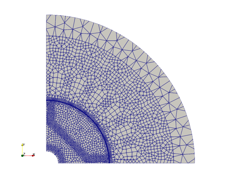
BDFから element geometry、property ID、bulk section、QVOL heat source を読み込みます。coil copper loss と PM loss はBDF QVOLを上書きせず、JSONから追加発熱として与えます。
Loss inputs
代表ケースで使用する発熱量は次の通りです。
| Source | Input method | Heat |
|---|---|---|
| BDF QVOL | QVOL_loss_mix.bdf | 1.091336675596593 W |
| Coil copper loss | thermal_volume_heat_sources, mode = "coil_copper_loss" | 23.004 W |
| PM magnet loss | thermal_volume_heat_sources, mode = "total_heat" | 1.25 W |
| Total | BDF QVOL + JSON volume heat | 25.345336675596593 W |
coil copper loss は相電流実効値と相抵抗から計算します。
P_phase = I_rms^2 * R_phase
        = 3.0^2 * 0.852
        = 7.668 W

P_total = 3 * P_phase = 23.004 W
各相の対象property IDは次の通りです。
| Phase | Property IDs |
|---|---|
| U | 10000, 10001 |
| V | 10004, 10005 |
| W | 10002, 10003 |
PM loss は永久磁石領域 property_id = 50000 に与えます。
| Region | Property ID | Heat input |
|---|---|---|
| Permanent magnet | 50000 | 5.0 W * 0.25 = 1.25 W |
coil_fill_factor は導体体積基準の発熱密度診断に使います。FEM RHSへ入れる I^2 R 損失を再スケールする値ではありません。
JSON cases
| JSON file | Purpose |
|---|---|
input_realistic_motor_steady_import_summary.json | BDF import、PSOLID/MAT diagnostics、QVOL heat、coil loss、PM lossを確認します。 |
input_realistic_motor_steady_all_external_balance.json | 全外表面をFEMH接続し、熱収支が閉じることを確認する基準ケースです。物理境界条件ではなく検証用です。 |
input_realistic_motor_steady_physical_no_gap.json | gap面を外部FEMH冷却から除外し、gap couplingなしで物理境界条件の基準を確認します。 |
input_realistic_motor_steady_physical_gap_h20.json | h = 20 W/m2/K のgap couplingを追加します。 |
input_realistic_motor_steady_physical_gap_nu1.json | mode = "nu", Nu = 1, k_air = 0.026 W/m/K, gap = 0.001 m でgap couplingを指定します。 |
input_realistic_motor_steady_physical_gap_h20_interface_resistance.json | coil/stator interface と PM/rotor interface に shared-node interface thermal resistance を追加します。 |
input_realistic_motor_steady_physical_gap_h20_interface_axial_endcool.json | 上下面から end_space_air へ逃げる軸方向端面冷却経路を追加します。coil-end heat escape の一次近似もこの経路で表現します。 |
input_realistic_motor_steady_mount_shaft_network.json | housing、mount、shaft、bearingを含む説明用thermal equivalent circuitです。係数は説明用の仮値です。 |
外側空気領域は熱FEMから除外します。
"bdf_import": {
  "exclude_property_ids": [50]
}
これにより、stator外周面をFEMH境界として housing や thermal equivalent circuit に接続できます。
Boundary conditions and FEMH connections
FEMHは、選択したFEM surface groupとthermal-network nodeを接続する境界条件です。これにより、housing、shaft、bearing、mount、ambientなどの集中定数熱回路ノードとFEM領域を連成できます。
物理境界条件ケースで主に使うsurface groupは次の通りです。
| Surface group | Typical use |
|---|---|
stator_external | stator側の全外表面。診断と差集合のbaseに使います。 |
rotor_external | rotor側の全外表面。診断と差集合のbaseに使います。 |
stator_gap_candidate_filtered | stator側gap候補面。gap coupling専用です。 |
rotor_gap_candidate_filtered | rotor側gap候補面。gap coupling専用です。 |
stator_external_cooling | gap面を除外したstator外部冷却面です。 |
rotor_external_cooling | gap面を除外したrotor外部冷却面です。 |
stator_radial_external_cooling | 端面とgap面を除外したstator外周冷却面です。 |
rotor_radial_external_cooling | 端面とgap面を除外したrotor外周冷却面です。 |
stator_end_faces | stator上下面です。end_space_airへ接続します。 |
rotor_end_faces | rotor上下面です。end_space_airへ接続します。 |
重要なルールは、gap couplingに使う面を外部FEMH冷却面として同時に使わないことです。
femh_and_gap_overlap area = 0
この値は thermal_surface_assignment_summary.csv で確認できます。
Gap thermal coupling
statorとrotorは熱FEM上では別componentです。gapを介した熱移動は、stator側gap面とrotor側gap面の surface-to-surface thermal coupling として扱います。
現在のサンプルでは node_pair_lumped assembly を使います。
- stator/rotor のgap face pairを抽出します。
- face pairごとに有効面積を計算します。
- 指定したmodeからconductanceを計算します。
- source/target face nodeを座標で対応付けます。
- 2節点間のlumped thermal conductanceとしてFEM行列へ組み込みます。
| Mode | Formula | Example |
|---|---|---|
h | G = h * A | h = 20 W/m2/K |
nu | h_equiv = Nu * k_air / gap_thickness | Nu = 1, k_air = 0.026 W/m/K, gap = 0.001 m |
Nu = 1 の例では次の値になります。
h_equiv = 26.0 W/m2/K
gap total conductance = 6.800205753006171e-02 W/K
Thermal equivalent circuit
熱等価回路は、FEM meshの外側にある冷却経路を集中定数で表現するためのものです。今回の図では、radial方向のhousing/shaft経路、stator/rotor gap経路、上下面からend spaceへ逃げる軸方向経路を示しています。
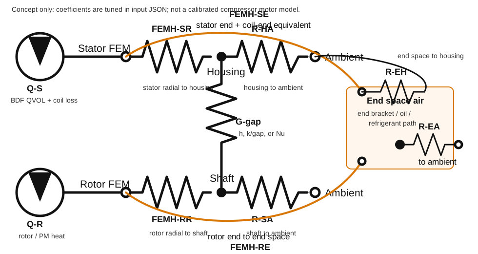
主な経路は次の通りです。
| Label | Meaning |
|---|---|
FEMH-SR | statorの非gap・非端面外周面から housing nodeへのFEMH接続です。 |
FEMH-RR | rotorの非gap・非端面外周面から shaft nodeへのFEMH接続です。 |
G-gap | stator/rotor gap surface couplingです。 |
FEMH-SE | stator上下面から end_space_air nodeへのFEMH接続です。一層押し出しモデルでは coil-end heat escape の一次近似としても扱います。 |
FEMH-RE | rotor上下面から end_space_air nodeへのFEMH接続です。 |
R-EH | end_space_air から housing へ逃げる端部空間の代表熱抵抗です。 |
R-EA | end_space_air から ambient へ逃げる代表熱抵抗です。 |
R-HA, R-SA | housing / shaft から ambient側へ向かう代表熱抵抗です。 |
FEMH portはFEM surface temperatureとthermal-network nodeを接続します。RTH/GTH elementはnetwork node間の熱抵抗または熱コンダクタンスです。
network node温度と熱流は次のCSVで確認できます。
thermal_network_nodes.csv
thermal_network_element_flows.csv
thermal_cooling_path_summary.csv
thermal_femh_ports.csv
Shared-node interface thermal resistance
節点共有メッシュで coil/stator core 境界や PM/rotor core 境界に熱抵抗を入れる例です。
input_realistic_motor_steady_physical_gap_h20_interface_resistance.json
この機能は、指定したproperty group間の内部faceを抽出し、指定した側の熱節点を複製して、元節点と複製節点の間にlumped thermal conductanceを入れます。磁界解析用に節点共有されたメッシュをそのまま使いながら、熱解析では界面温度不連続を表現できます。
入力例です。
"interface_thermal_resistances": [
  {
    "name": "coil_to_stator_slot_liner",
    "side_a": { "property_ids": [10] },
    "side_b": { "property_ids": [10000, 10001, 10002, 10003, 10004, 10005] },
    "split_side": "side_b",
    "mode": "thin_layer",
    "layer_thermal_conductivity": 0.2,
    "layer_thickness": 0.0002,
    "assembly": "shared_node_pair_lumped"
  },
  {
    "name": "pm_to_rotor_adhesive",
    "side_a": { "property_ids": [20] },
    "side_b": { "property_ids": [50000] },
    "split_side": "side_b",
    "mode": "thin_layer",
    "layer_thermal_conductivity": 0.2,
    "layer_thickness": 0.0002,
    "assembly": "shared_node_pair_lumped"
  }
]
代表値は次の通りです。
| Interface | Faces | Area | h_equiv | Total conductance | Equivalent resistance |
|---|---|---|---|---|---|
| coil_to_stator_slot_liner | 156 | 1.187038579243427e-02 m2 | 1000 W/m2/K | 1.187038579243424e+01 W/K | 8.424326028538720e-02 K/W |
| pm_to_rotor_adhesive | 80 | 2.399721226189904e-03 m2 | 1000 W/m2/K | 2.399721226189901e+00 W/K | 4.167150705199728e-01 K/W |
確認するCSVです。
thermal_interface_resistance_summary.csv
thermal_interface_resistance_node_pairs.csv
thermal_interface_resistance_node_splits.csv
thermal_matrix_diagnostics.csv
thermal_global_heat_balance.csv
Axial end-space cooling and coil-end equivalent path
input_realistic_motor_steady_physical_gap_h20_interface_axial_endcool.json は、shared-node interface thermal resistanceに加えて、軸方向の上下面から熱が逃げる経路を追加したケースです。
2D断面を軸方向に一層押し出した簡易モデルでは、実機3Dモデルに存在するend space、end bracket、oil、refrigerant側への熱流が不足しやすくなります。このケースでは、その不足を補うために上下面を end_space_air nodeへ接続します。
設定方針は次の通りです。
- 外側空気 property
50は熱FEM領域から除外します。 stator_radial_external_coolingは stator の非gap・非端面外周面としてhousingnodeへFEMH接続します。rotor_radial_external_coolingは rotor の非gap・非端面外周面としてshaftnodeへFEMH接続します。stator_end_facesとrotor_end_facesはabs_normal_z_min = 0.9で抽出し、end_space_airnodeへFEMH接続します。end_space_airはhousingおよびambientへthermal resistanceで接続します。
このケースでは、コイルエンドを直接3D形状として作る代わりに、stator端面側のFEMH経路を「slot coil / stator end region から end space air へ逃げる代表経路」として扱っています。より詳細な評価では、coil endを別領域または熱等価回路ノードとして表現し、coil end loss と coil end cooling path を分けることを想定します。
代表結果です。
| Quantity | Value |
|---|---|
| stator radial cooling avg. temperature | 67.55 degC |
| stator end faces avg. temperature | 72.67 degC |
| rotor radial cooling avg. temperature | 44.38 degC |
| rotor end faces avg. temperature | 44.71 degC |
| stator gap avg. temperature | 67.92 degC |
| rotor gap avg. temperature | 52.15 degC |
| gap heat source-to-target | 0.824813796 W |
| global relative residual | 3.782002356724577e-11 |
このケースは、compressor motorの実測合わせ済みモデルではなく、境界条件設定を説明するためのサンプルです。FEMH係数とthermal-network resistanceは、実測case温度、冷媒/油の状態、end-space geometry、3D validation dataを使って調整してください。
Temperature result
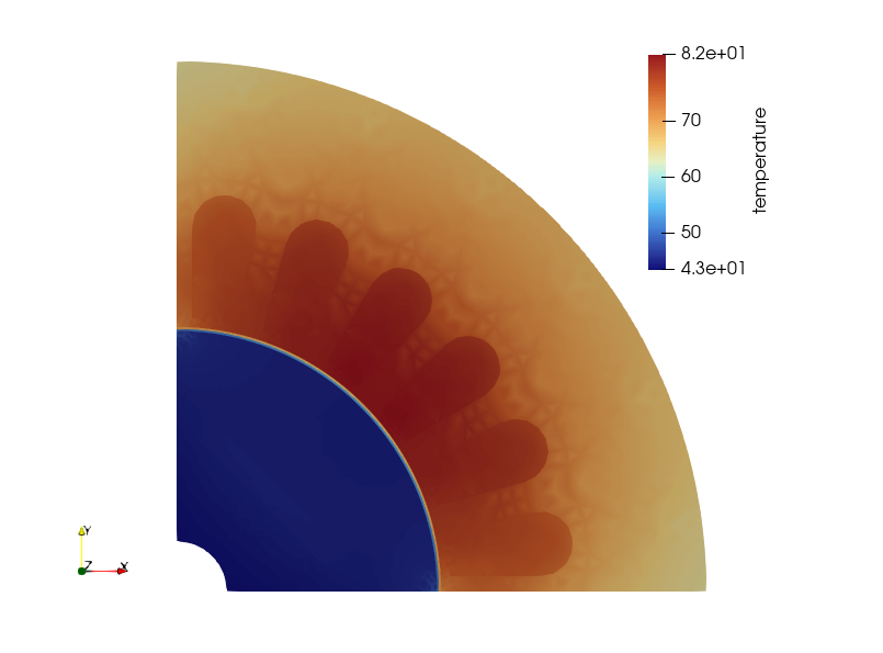
この図は、端面冷却とcoil-end相当経路を含む代表的な温度分布です。カラーバーは自動調整した表示例であり、絶対温度は仮のFEMH係数と熱等価回路係数に依存します。
重要なのは、loss total、heat balance、surface overlap、cooling pathをCSVで追跡できることです。
Gap area result
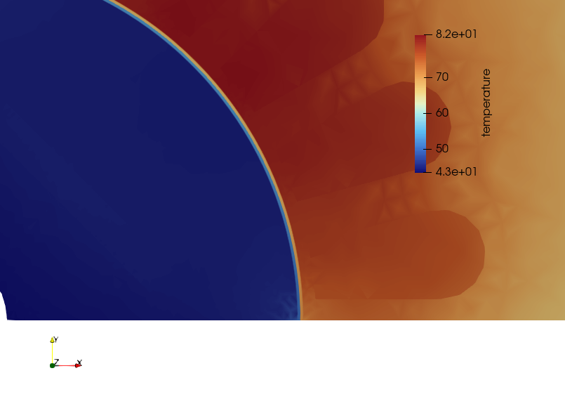
Gap couplingに使う面は、外部FEMH cooling surfaceから除外します。thermal_surface_assignment_summary.csv で femh_and_gap_overlap area = 0 を確認してください。
Heat balance checks
まず input_realistic_motor_steady_all_external_balance.json で、損失合計と流出熱量が一致することを確認します。
FEM volume heat       = 25.345336675596593 W
FEM RHS heat          = 25.345336675596593 W
FEMH outflow          ~= 25.345336675596593 W
network TEMP outflow  ~= 25.345336675596593 W
global relative residual ~= 1e-11
端面冷却ケースでは、代表的に次のような値になります。
FEM RHS heat             = 25.34533667559660 W
FEMH outflow             = 25.34533667438468 W
network TEMP outflow     = 25.34533667463804 W
global relative residual = 3.782002356724577e-11
CSV files to check
thermal_volume_heat_sources.csv
thermal_fem_volume_heat.csv
thermal_global_heat_balance.csv
thermal_surface_assignment_summary.csv
thermal_surface_temperature_summary.csv
thermal_component_heat_balance.csv
thermal_cooling_path_summary.csv
thermal_gap_coupling_summary.csv
thermal_gap_coupling_flow_summary.csv
thermal_network_nodes.csv
thermal_network_element_flows.csv
thermal_femh_ports.csv