Realistic Motor Steady Thermal Sample
This showcase explains a steady-state motor thermal workflow using a mixed CHEXA/CPENTA BDF mesh, imported QVOL losses, JSON-defined additional losses, FEMH surface cooling, a thermal equivalent circuit, and stator/rotor gap coupling.
The purpose of this example is not to match a measured motor temperature. Instead, it demonstrates how to set up and audit the complete thermal path for an electric-machine design model:
- loss input from BDF
QVOL - coil copper loss from phase current and resistance
- permanent-magnet loss from a user-specified total heat value
- FEMH connection from selected FEM surfaces to thermal-network nodes
- stator/rotor air-gap thermal coupling
- surface assignment diagnostics to avoid double-counted boundary faces
- component heat balance, cooling path summary, and network-node temperatures
The public example is located under:
Examples/thermal/realistic_motor_steady/
The BDF used by the sample is included in that folder as:
Examples/thermal/realistic_motor_steady/QVOL_loss_mix.bdf
Model And Mesh
The motor thermal mesh is a BDF model with mixed solid elements. It contains two bulk sections that are treated as separate thermal components:
| Component | Bulk section | Role |
|---|---|---|
| Stator | 0 | Stator core, slot coil regions, and stator-side losses. |
| Rotor | 1 | Rotor core, permanent magnet region, and rotor-side losses. |
The figure below shows the motor mesh used in the showcase.
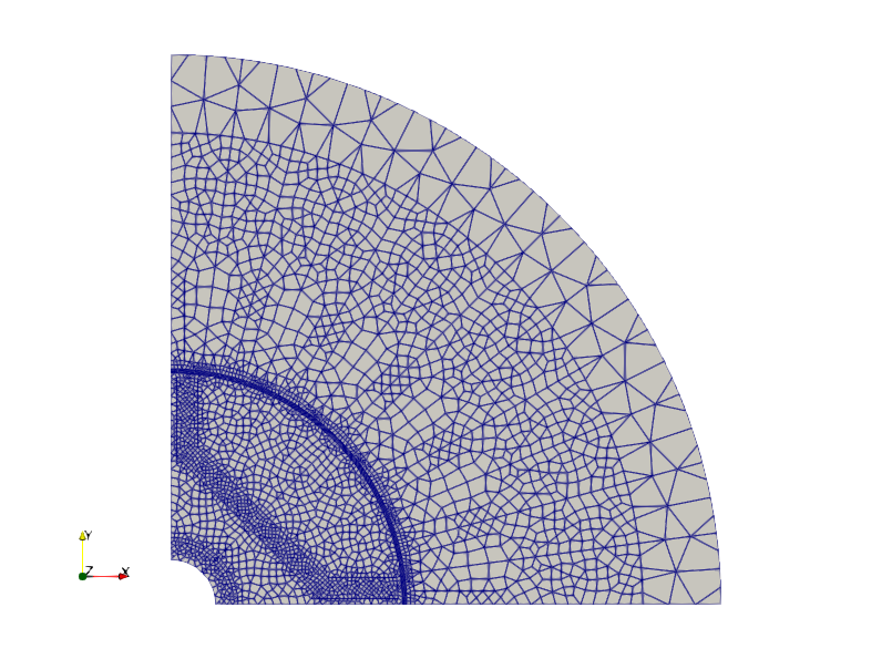
The mesh is used as a thermal conduction model. The BDF provides element geometry, property IDs, bulk sections, and QVOL heat sources. Additional engineering heat sources are added from JSON rather than overwriting the BDF QVOL data.
Loss Inputs
The total heat in the main realistic cases is:
| Source | Input method | Heat |
|---|---|---|
| BDF QVOL | Imported from QVOL_loss_mix.bdf | 1.091336675596593 W |
| Coil copper loss | thermal_volume_heat_sources, mode = "coil_copper_loss" | 23.004 W |
| PM magnet loss | thermal_volume_heat_sources, mode = "total_heat" | 1.25 W |
| Total | BDF QVOL + JSON volume heat | 25.345336675596593 W |
The BDF QVOL heat is the loss already exported by the upstream electromagnetic workflow. In this sample, the coil copper loss is added in JSON because the electromagnetic model uses external circuit resistance for the coil conductor.
The coil copper loss is computed from RMS phase current and phase resistance:
P_phase = I_rms^2 * R_phase
        = 3.0^2 * 0.852
        = 7.668 W

P_total = 3 * P_phase = 23.004 W
The phase target property IDs are:
| Phase | Property IDs |
|---|---|
| U | 10000, 10001 |
| V | 10004, 10005 |
| W | 10002, 10003 |
The PM loss is assigned to:
| Region | Property ID | Heat input |
|---|---|---|
| Permanent magnet | 50000 | 5.0 W * 0.25 = 1.25 W |
The coil_fill_factor is used for diagnostic conductor-volume heat density. It
does not rescale the I^2 R copper loss that is assembled into the FEM right
hand side.
JSON Cases
The directory contains several JSON files. Each one is useful for a different stage of model checking.
| JSON file | Purpose |
|---|---|
input_realistic_motor_steady_import_summary.json | Check BDF import, PSOLID/MAT diagnostics, QVOL heat, coil loss, and PM loss. |
input_realistic_motor_steady_all_external_balance.json | Connect all external faces by FEMH to verify closed heat balance. This is a verification boundary condition, not a physical cooling model. |
input_realistic_motor_steady_physical_no_gap.json | Exclude gap faces from external FEMH cooling and run physical-style external cooling without stator/rotor gap coupling. |
input_realistic_motor_steady_physical_gap_h20.json | Use physical-style external cooling plus air-gap coupling with direct h = 20 W/m2/K. |
input_realistic_motor_steady_physical_gap_nu1.json | Use physical-style external cooling plus air-gap coupling with mode = "nu", Nu = 1, k_air = 0.026 W/m/K, and gap = 0.001 m. |
input_realistic_motor_steady_physical_gap_h20_interface_resistance.json | Add shared-node interface thermal resistance for coil-to-stator and PM-to-rotor interfaces. |
input_realistic_motor_steady_physical_gap_h20_interface_axial_endcool.json | Add axial end-face cooling paths through an end_space_air network node, representing first-order end-space and coil-end heat escape. |
input_realistic_motor_steady_mount_shaft_network.json | Demonstrate a housing, mount, shaft, and bearing thermal equivalent circuit. Values are illustrative, not calibrated. |
All realistic motor cases exclude the outer air property from the thermal FEM domain:
"bdf_import": {
  "exclude_property_ids": [50]
}
The BDF still contains the outer air region for electromagnetic meshing, but thermal conduction is solved only in the motor solids. This makes the stator outer surface available as the FEMH boundary connected to the housing or thermal equivalent circuit.
Boundary Conditions And FEMH Connections
FEMH connects selected FEM surface groups to thermal-network nodes. This lets the FEM model exchange heat with lumped thermal-circuit nodes such as housing, shaft, bearing, mount, and ambient.
In the physical boundary examples, the main surface groups are:
| Surface group | Typical use |
|---|---|
stator_external | All stator external faces. Used for diagnostics and set operations. |
rotor_external | All rotor external faces. Used for diagnostics and set operations. |
stator_gap_candidate_filtered | Stator-side air-gap candidate faces. Used for gap coupling only. |
rotor_gap_candidate_filtered | Rotor-side air-gap candidate faces. Used for gap coupling only. |
stator_external_cooling | Stator external cooling surface after excluding gap faces. Connected to housing by FEMH. |
rotor_external_cooling | Rotor external cooling surface after excluding gap faces. Connected to shaft by FEMH. |
The important modeling rule is:
Gap faces must not also be used as external FEMH cooling faces.
The model checks this with:
thermal_surface_assignment_summary.csv
For the physical gap cases, the intended result is:
femh_and_gap_overlap area = 0
If this value is not zero, the same face is carrying both external cooling and stator/rotor internal gap heat exchange, which double-counts the thermal path.
Gap Thermal Coupling
The stator and rotor meshes are separate thermal components. The air-gap heat path is represented by a surface-to-surface thermal coupling between paired gap faces.
The current implementation uses node_pair_lumped assembly:
- Pair accepted stator and rotor gap faces.
- Compute effective pair area.
- Compute pair conductance from the chosen model.
- Match source and target face nodes by nearest coordinates.
- Stamp lumped two-node thermal conductances into the FEM matrix.
This showcase demonstrates two common input styles:
| Mode | Formula | Example |
|---|---|---|
h | G = h * A | h = 20 W/m2/K |
nu | h_equiv = Nu * k_air / gap_thickness | Nu = 1, k_air = 0.026 W/m/K, gap = 0.001 m |
For the Nu = 1 case:
h_equiv = 26.0 W/m2/K
gap total conductance = 6.800205753006171e-02 W/K
Thermal Equivalent Circuit
The thermal equivalent circuit represents cooling paths outside the FEM mesh. The updated concept diagram includes the radial housing/shaft paths, the stator/rotor gap path, and an axial end-space path used to approximate heat escape through the upper/lower motor end regions.
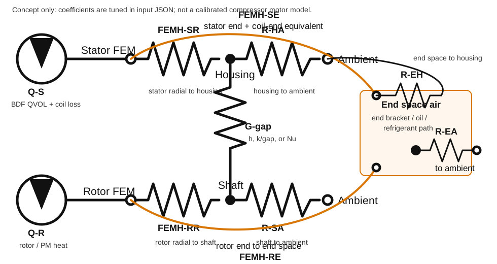
The main paths are:
| Label | Meaning |
|---|---|
FEMH-SR | FEMH connection from stator radial external surfaces to the housing node. |
FEMH-RR | FEMH connection from rotor radial external surfaces to the shaft node. |
G-gap | Surface-to-surface stator/rotor gap thermal coupling. |
FEMH-SE | FEMH connection from stator end faces to end_space_air; in this one-layer extruded sample it also represents a first-order coil-end heat-escape path. |
FEMH-RE | FEMH connection from rotor end faces to end_space_air. |
R-EH | Thermal resistance from end_space_air to housing. |
R-EA | Thermal resistance from end_space_air to ambient. |
R-HA, R-SA | Representative housing/shaft paths to ambient. |
FEMH ports form conductance paths between FEM surface temperatures and thermal-network nodes. RTH/GTH elements then move heat between network nodes. The gap surface is not also used as an external FEMH cooling surface; it is handled as an internal surface-to-surface heat-exchange path.
To inspect the thermal-network temperatures and heat flows, open:
thermal_network_nodes.csv
thermal_network_element_flows.csv
thermal_cooling_path_summary.csv
thermal_femh_ports.csv
The axial end-space case is:
input_realistic_motor_steady_physical_gap_h20_interface_axial_endcool.json
Representative values for that case are:
| Quantity | Value |
|---|---|
| stator radial cooling average temperature | 67.55 degC |
| stator end faces average temperature | 72.67 degC |
| rotor radial cooling average temperature | 44.38 degC |
| rotor end faces average temperature | 44.71 degC |
| stator gap average temperature | 67.92 degC |
| rotor gap average temperature | 52.15 degC |
| gap heat source-to-target | 0.824813796 W |
| global relative residual | 3.782002356724577e-11 |
The coefficients are illustrative. For a compressor motor, tune FEMH coefficients and network resistances using measured case temperature, coolant/oil condition, end-space geometry, and 3D validation data.
Temperature Results
The figure below shows a representative steady-state temperature field for the physical boundary case with air-gap coupling.
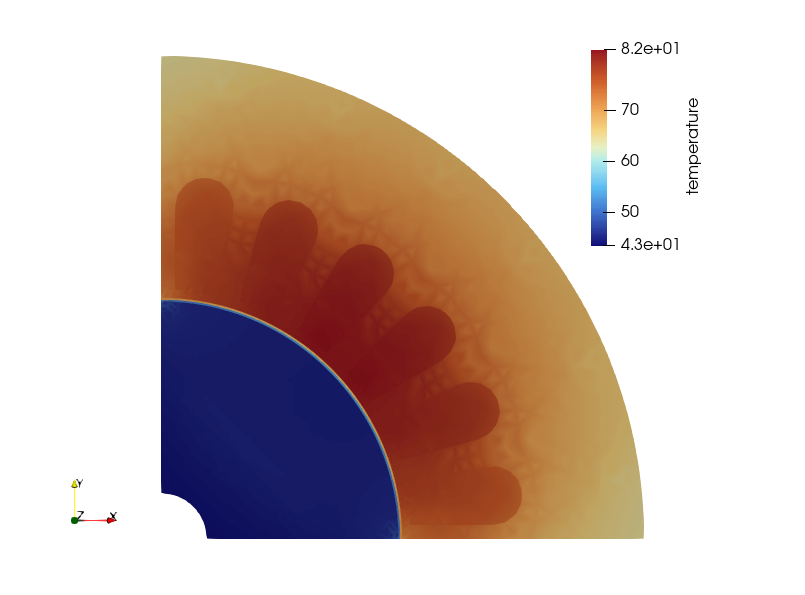
The highest temperatures occur on the stator side in this illustrative setup because most of the added heat is coil copper loss. This does not mean the absolute values are calibrated to a real machine. The example is designed to show how heat sources and heat-flow paths can be audited.
The next figure focuses on the gap region.
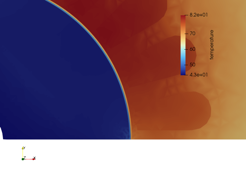
Use this view together with thermal_gap_coupling_flow_summary.csv and
thermal_gap_coupling_flows.csv to confirm that the sign and magnitude of gap
heat flow are consistent with the stator and rotor gap-surface temperatures.
For the h = 20 W/m2/K gap case, representative values are:
| Quantity | Value |
|---|---|
| Accepted gap face pairs | 90 |
| Gap total conductance | 5.230927502312448e-02 W/K |
| Equivalent gap resistance | 19.11706861847976 K/W |
| Gap heat source-to-target | 2.181396948282994 W |
| Surface overlap area | 0 |
For the Nu = 1 case:
| Quantity | Value |
|---|---|
Nu | 1.0 |
h_equiv | 26.0 W/m2/K |
| Gap total conductance | 6.800205753006171e-02 W/K |
| Gap heat source-to-target | 2.332210259864751 W |
Heat Balance Checks
Start with the all-external balance case before interpreting physical boundary conditions. It checks that all heat sources enter the FEM right-hand side and leave through FEMH/network paths.
Representative balance:
FEM volume heat       = 25.34533667559660 W
FEM RHS heat          = 25.34533667559660 W
FEMH outflow          = 25.34533667548905 W
network TEMP outflow  = 25.34533667547321 W
global relative residual ~ 1e-11
For component-level checks, inspect:
thermal_component_heat_balance.csv
For the h = 20 W/m2/K physical gap case:
| Component | QVOL and JSON heat | FEMH outflow | Net gap heat outflow | Average temperature |
|---|---|---|---|---|
| Stator | 23.9886 W | 21.8072 W | 2.1814 W | 187.839 C |
| Rotor | 1.3567 W | 3.5381 W | -2.1814 W | 114.653 C |
The positive stator gap heat outflow and negative rotor net gap heat outflow show that heat is flowing from the hotter stator-side gap surface to the rotor side in this illustrative case.
Output Files To Inspect
| File | What to check |
|---|---|
thermal_bdf_import_summary.csv | BDF import counts, QVOL counts, total BDF heat. |
thermal_bdf_property_material_summary.csv | PSOLID/MAT diagnostics and analysis material source. |
thermal_volume_heat_sources.csv | Coil copper loss, PM loss, assigned heat density, target volume. |
thermal_fem_volume_heat.csv | BDF QVOL heat, JSON added heat, and total FEM volume heat. |
thermal_global_heat_balance.csv | Total heat input, FEMH outflow, network outflow, residual. |
thermal_surface_assignment_summary.csv | FEMH/gap overlap and unassigned external area. |
thermal_surface_temperature_summary.csv | Area-weighted surface temperatures. |
thermal_gap_pair_summary.csv | Gap face pairing count and quality. |
thermal_gap_coupling_summary.csv | Assembled gap conductance and equivalent resistance. |
thermal_gap_coupling_flow_summary.csv | Total heat transferred through the gap coupling. |
thermal_cooling_path_summary.csv | FEMH and gap path conductance, temperatures, and heat flow. |
thermal_network_nodes.csv | Thermal equivalent-circuit node temperatures. |
thermal_network_element_flows.csv | Heat flow through thermal-network RTH/GTH elements. |
mesh.vtk | Mesh geometry, property IDs, and element IDs. |
thermal_result.vtk | Temperature field for ParaView. |
boundary_faces.vtk | Surface-group and cooling-boundary visualization. |
Modeling Notes
This sample intentionally uses illustrative coefficients. Before using a similar setup for design decisions, review:
- actual coil resistance and current conditions
- modeled axial-length fraction
- PM loss source and modeled fraction
- material thermal conductivities
- FEMH heat transfer coefficients
- housing, shaft, bearing, and mount thermal resistances
- gap heat-transfer model, such as measured
h,k/gap, externalNu, or a user-defined preprocessing workflow - surface assignment overlap
- mesh density in regions with steep thermal gradients
Temperature-dependent material properties, transient thermal analysis, radiation, automatic coil-end loss distribution, and calibrated rotating-gap correlations are outside the scope of this showcase.
Shared-node interface thermal resistance
The sample also includes an optional shared-node interface resistance case:
input_realistic_motor_steady_physical_gap_h20_interface_resistance.json
This case is intended for meshes where adjacent parts share nodes, such as coil-to-stator-core or PM-to-rotor-core interfaces. The input extracts matching internal faces from the specified property groups, duplicates the nodes on the selected side for the thermal solve, and stamps a lumped conductance between the original and duplicated thermal nodes.
Example input fragment:
"interface_thermal_resistances": [
  {
    "name": "coil_to_stator_slot_liner",
    "side_a": { "property_ids": [10] },
    "side_b": { "property_ids": [10000, 10001, 10002, 10003, 10004, 10005] },
    "split_side": "side_b",
    "mode": "thin_layer",
    "layer_thermal_conductivity": 0.2,
    "layer_thickness": 0.0002,
    "assembly": "shared_node_pair_lumped"
  },
  {
    "name": "pm_to_rotor_adhesive",
    "side_a": { "property_ids": [20] },
    "side_b": { "property_ids": [50000] },
    "split_side": "side_b",
    "mode": "thin_layer",
    "layer_thermal_conductivity": 0.2,
    "layer_thickness": 0.0002,
    "assembly": "shared_node_pair_lumped"
  }
]
Representative validation values for this sample are:
| Interface | Faces | Area | h_equiv | Total conductance | Equivalent resistance |
|---|---|---|---|---|---|
| coil_to_stator_slot_liner | 156 | 1.187038579243427e-02 m2 | 1000 W/m2/K | 1.187038579243424e+01 W/K | 8.424326028538720e-02 K/W |
| pm_to_rotor_adhesive | 80 | 2.399721226189904e-03 m2 | 1000 W/m2/K | 2.399721226189901e+00 W/K | 4.167150705199728e-01 K/W |
Check these CSV files when using interface resistance:
thermal_interface_resistance_summary.csv
thermal_interface_resistance_node_pairs.csv
thermal_interface_resistance_node_splits.csv
thermal_matrix_diagnostics.csv
thermal_global_heat_balance.csv
Axial End-Space Cooling And Coil-End Equivalent Path
input_realistic_motor_steady_physical_gap_h20_interface_axial_endcool.json adds axial heat-escape paths on top of the shared-node interface-resistance case. This is useful for a one-layer extruded 2D motor sample, where heat that would leave through the upper/lower end regions of a real 3D motor can otherwise be underrepresented.
The modeling approach is:
- Exclude the outer air property
50from the thermal FEM domain. - Connect
stator_radial_external_coolingto thehousingnode through FEMH. - Connect
rotor_radial_external_coolingto theshaftnode through FEMH. - Extract
stator_end_facesandrotor_end_faceswithabs_normal_z_min = 0.9. - Connect those end faces to an
end_space_airnode through FEMH. - Connect
end_space_airtohousingandambientthrough thermal resistances.
In this first-stage sample, the stator end-face FEMH path is also used as a practical equivalent path for slot coil and coil-end heat escape. A more detailed future model can split the coil end into its own thermal-network node or 3D region, then assign coil-end loss and cooling separately.
Representative result:
| Quantity | Value |
|---|---|
| stator radial cooling average temperature | 67.55 degC |
| stator end faces average temperature | 72.67 degC |
| rotor radial cooling average temperature | 44.38 degC |
| rotor end faces average temperature | 44.71 degC |
| stator gap average temperature | 67.92 degC |
| rotor gap average temperature | 52.15 degC |
| gap heat source-to-target | 0.824813796 W |
| global relative residual | -9.996386288e-12 |
The values are illustrative rather than calibrated. For a compressor motor, tune FEMH coefficients and network resistances using measured case temperature, coolant/oil condition, end-space geometry, and 3D validation data.