Structural Rotor Samples
This showcase explains the structural rotor examples in eMachineSim. The sample is intended for electric-machine rotor design workflows where centrifugal force, shaft/support constraints, and simple contact diagnostics need to be checked before moving to more detailed verification.
The public examples are located under:
Examples/structural/rotor/
Representative JSON inputs are:
input_rotor_2d_1500rpm_smoke.json
input_rotor_2d_3000rpm_smoke.json
input_rotor_2d_1500rpm_shaft_bc_no_contact.json
input_rotor_core_only_2d_1500rpm.json
input_rotor_core_only_2d_modal.json
Even when the input mesh uses first-order elements, setting "ELEMENT_ORDER": 2 in 6_Gaussian_Integral_Point converts the mesh to second-order elements during preprocessing. The post-processing mesh is also written as second-order elements.
Model Description
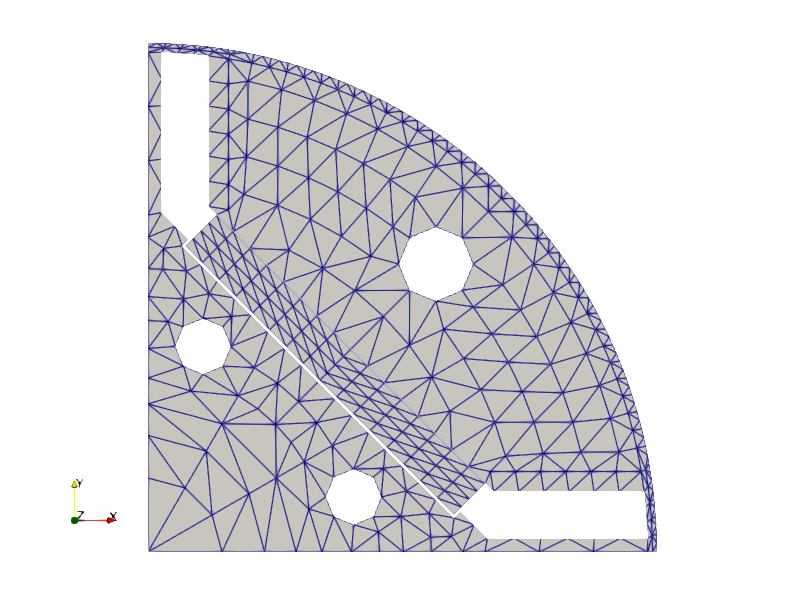
The example uses a 2D rotor cross-section model. It includes the rotor core, magnet-related regions, flux-barrier boundaries, and structural boundary conditions for a centrifugal-force load case. The current public mesh uses a merged magnet/core interface: the permanent-magnet nodes have been moved to the rotor-core side and node-merged at the interface. This represents the assumption that magnetic attraction keeps the magnet attached to the rotor core for this basic centrifugal-force sample.
The figure below shows the input mesh.
Static Structural Conditions
The primary static sample for the merged mesh is:
input_rotor_2d_1500rpm_shaft_bc_no_contact.json
The main settings are:
| Item | Setting |
|---|---|
| Analysis type | Static structural analysis |
| Structural assumption | 2D plane stress |
| Thickness | 1.0 m |
| Rotation speed | 1500 rpm equivalent |
| Angular velocity | 157.079632679 rad/s around the z-axis |
| Material Young's modulus | 205 GPa |
| Poisson's ratio | 0.3 |
| Density | 7800 kg/m3 |
| Magnet/core interface | Shared-node merged interface |
| Contact model | Disabled for the primary merged-mesh case |
The sample includes displacement boundary conditions and a centrifugal body
force. Because the magnet/core interface is node-merged, the primary case treats
that interface as a tied or perfectly bonded interface. No penalty contact is
assembled for that interface in input_rotor_2d_1500rpm_shaft_bc_no_contact.json.
Sector Model Constraints
For 45-degree, 90-degree, 120-degree, 180-degree, and similar sector models,
STRUCTURAL_CYCLIC_SECTOR_BC can automatically extract the minimum-angle and
maximum-angle periodic boundaries from the boundary nodes. For centrifugal-force
rotor checks, a common setup is to allow radial displacement and constrain only
the tangential direction on the sector boundaries.
When the shaft is not meshed in an inner-rotor model, STRUCTURAL_RADIAL_SUPPORT_BC
can be used as a simplified shaft support. It removes the periodic-boundary
nodes from the boundary-node candidates, extracts the minimum-radius node row
for SIDE: "INNER", and applies the selected cylindrical-coordinate constraints
with a penalty method.
Example settings for a 45-degree sector model:
"STRUCTURAL_CYCLIC_SECTOR_BC": {
  "ENABLED": 1,
  "AUTO_DETECT": 1,
  "AXIS_POINT": [0.0, 0.0, 0.0],
  "MIN_RADIUS": 1e-8,
  "FIX_RADIAL": 0,
  "FIX_TANGENTIAL": 1,
  "FIX_UZ": 0,
  "PENALTY_STIFFNESS": 1e15
},
"STRUCTURAL_RADIAL_SUPPORT_BC": {
  "ENABLED": 1,
  "AUTO_DETECT": 1,
  "SIDE": "INNER",
  "AXIS_POINT": [0.0, 0.0, 0.0],
  "EXCLUDE_CYCLIC_SECTOR_NODES": 1,
  "RADIUS_TOLERANCE_ABS": 1e-6,
  "RADIUS_TOLERANCE_REL": 1e-4,
  "FIX_RADIAL": 1,
  "FIX_TANGENTIAL": 0,
  "FIX_UZ": 0,
  "PENALTY_STIFFNESS": 1e15
}
The run writes structural_cyclic_sector_constraints.csv and
structural_radial_support_constraints.csv, which list the detected nodes,
radius, angle, and constrained directions.
Run the static structural case from Python:
import eMachineSim

result = eMachineSim.structural.solve(
    r"Examples\structural\rotor\input_rotor_2d_1500rpm_shaft_bc_no_contact.json",
    r"Examples\structural\rotor",
)
print(result["success"])
Result Visualization
The structural post-processing path writes VTK files that can be opened in ParaView:
| File | Purpose |
|---|---|
mesh.vtk | Rotor mesh geometry and property IDs. |
structural_displacement.vtk | Displacement vector, displacement magnitude, and von Mises stress arrays. |
boundary_faces.vtk | Boundary face visualization for constraints and diagnostics. |
contact_debug.vtk | Contact visualization output when a contact-diagnostic variant is enabled. |
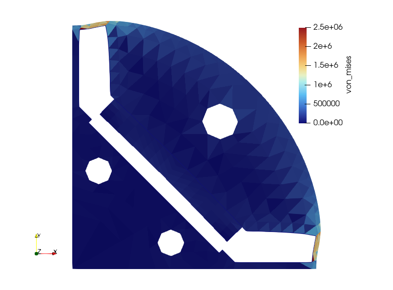
Use ParaView's Warp By Vector filter with the displacement vector to view
the deformed shape. The figure below shows a representative displacement result.
This plot is useful for quickly checking:
- whether the rotor deforms in the expected radial direction,
- whether the displacement field is smooth,
- whether constraints are too strong or too weak,
- whether contact regions remain visually reasonable.
The absolute deformation shown in the figure depends on the chosen ParaView warp scale factor. Use the numerical output files for quantitative checks.
Load and Interface Diagnostics
After the run, inspect the CSV diagnostics in the same directory.
| File | Purpose |
|---|---|
structural_load_balance.csv | Applied load and reaction-balance summary. |
contact_state.csv | Contact gap, penetration, normal force, and pressure by contact entity, when a contact variant is enabled. |
contact_penalty_assembly.csv | Contact penalty assembly diagnostics, when a contact variant is enabled. |
boundary_faces.csv | Boundary face table used for constraints and surface diagnostics. |
For the current merged-mesh 1500 rpm no-contact case, representative
load-balance values are:
| Quantity | Fx [N] | Fy [N] | Fz [N] |
|---|---|---|---|
| Centrifugal body force | 1.1563e3 | 1.1683e3 | 0 |
| Total applied | 1.1563e3 | 1.1683e3 | 0 |
| Reaction balance estimate | -1.1563e3 | -1.1683e3 | 0 |
The merged interface should be interpreted as a tied interface. In other words, the magnet and rotor-core nodes on the interface share the same displacement unknowns. This avoids the artificial "floating magnet" behavior that can appear when a separated magnet body is loaded by centrifugal force without a physically appropriate retaining path. The contact-enabled JSON files are retained as diagnostic variants, but they are no longer the recommended interpretation for this merged-interface showcase.
Case Variants
The rotor directory contains several variants:
| JSON file | Purpose |
|---|---|
input_rotor_2d_1500rpm_smoke.json | Contact-diagnostic variant retained for implementation checks. |
input_rotor_2d_3000rpm_smoke.json | Higher-speed centrifugal-force variant. |
input_rotor_2d_1500rpm_shaft_bc_no_contact.json | Primary merged-interface centrifugal-force case. |
input_rotor_core_only_2d_1500rpm.json | Core-only centrifugal structural case. |
input_rotor_core_only_2d_modal.json | Core-only modal check. |
Use these variants to separate effects:
- compare
1500 rpmand3000 rpmto check centrifugal-force scaling, - use the no-contact merged-interface case for the basic magnet/core attached assumption,
- use contact variants only when you intentionally want to inspect the current penalty-contact diagnostic path,
- use core-only cases for simpler baseline debugging.
Interpretation Notes
This showcase is designed to demonstrate workflow and diagnostics. Before using similar inputs for design decisions, review:
- material properties and density,
- plane-stress or plane-strain assumption,
- actual rotor axial length or thickness,
- shaft and support boundary conditions,
- contact stiffness and tolerance,
- mesh density around magnets and bridges.
The mesh used in this showcase is derived from a magnetic-field-analysis mesh. It may therefore be relatively coarse at structural stress-concentration locations. If the von Mises stress appears concentrated in a single element, use a refined structural mesh around the local stress-gradient region before drawing quantitative design conclusions.
For publication-quality or design-signoff stress values, use a sufficiently refined model and validate boundary conditions against the intended operating condition.