
17.1 External Current Field Source#
Defines the external-current field source COIL, which can be defined independently of the finite-element mesh. COIL can define a coil or field source using the Biot–Savart law.
The region in which COIL is created is assumed to be an air region. Define the coil geometry within the reduced-potential region specified by POTENTIAL(16.1).
Settings#
COIL(17.1) Specifies the external-current field source COIL.
SERIES_ID(17.1)COIL series ID.
TIME_ID(17.1)COIL time-definition ID.
MOTION_ID(17.1)COIL motion ID when MOTION = 1.
IN_ROTOR(17.1)Flag indicating whether the source is in the rotor.
POTENTIAL(17.1)Reduced-potential ID.
TO_MESHED_COIL(17.1)Flag for converting to a meshed coil.
data(17.1)COIL definition data.
TYPE(17.1)Data type.
UNIF(17.1.1)Uniform-field definition.
B_XYZ(17.1.1)XYZ components of the normalized uniform flux density.
A_FORM(17.1.1)Representation of the uniform field as a magnetic vector potential.
LOOP(17.1.2)Axisymmetric rectangular-cross-section coil definition.
CURRENT(17.1.2)Normalized current value.
RADIUS(17.1.2)Mean radius.
CENTER_Z(17.1.2)z coordinate of the center.
RADIAL_W(17.1.2)Radial width.
AXIAL_W(17.1.2)Axial width.
GCE(17.1.3)Rectangular-prism current-element definition.
CURRENT(17.1.3)Normalized current value.
S_XYZ(17.1.3)Start-point coordinates.
E_XYZ(17.1.3)End-point coordinates.
W1_XYZ(17.1.3)Width at the start point.
W2_XYZ(17.1.3)Width at the end point.
ARC(17.1.4)Arc-coil definition.
CURRENT(17.1.4)Normalized current value.
XYZ(17.1.4)Start-point coordinates.
RADIUS(17.1.4)Radius.
AXIAL_W(17.1.4)Axial width.
RADIAL_W(17.1.4)Radial width.
ALPHA(17.1.4)Euler angle α
BETA(17.1.4)Euler angle β
PHI1(17.1.4)Start angle measured from the x2 axis.
PHI2(17.1.4)End angle measured from the x2 axis.
FGCE(17.1.5)Straight-line coil definition.
CURRENT(17.1.5)Normalized current value.
S_XYZ(17.1.5)Start-point coordinates.
E_XYZ(17.1.5)End-point coordinates.
FARC(17.1.6)Arc-line coil definition.
CURRENT(17.1.6)Normalized current value.
XYZ0(17.1.6)Start-point coordinates.
RADIUS(17.1.6)Radius.
ALPHA(17.1.6)Euler angle α.
BETA(17.1.6)Euler angle β.
PHI1(17.1.6)Start angle measured from the x2 axis.
PHI2(17.1.6)End angle measured from the x2 axis.
MESH(17.1.7)Meshed-coil definition.
CURRENT(17.1.7)Normalized current value.
MESH_ID(17.1.7)Mesh ID.
LOOP-(17.1.8)Rectangular-cross-section coil definition.
GCE-(17.1.8)Rectangular-prism current-element definition.
ARC-(17.1.8)Arc-coil definition.
MESH-(17.1.8)Meshed-coil definition.
INT_X(17.1.8)Number of Gaussian integration points in the X direction
INT_Y(17.1.8)Number of Gaussian integration points in the Y direction
INT_Z(17.1.8)Number of Gaussian integration points in the Z direction
LINE(17.1.9)Line-coil definition.
CURRENT(17.1.9)Normalized current value.
XYZ0(17.1.9)Coordinates of a point through which the line passes
DXYZ(17.1.9)Components of the line direction vector
DIPO(17.1.10)Magnetic-dipole coil definition.
DBZDX(17.1.10)Normalized x-direction gradient of the z-direction magnetic field
EXMAG(17.1.11)Permanent-magnet definition.
READ_OPTION(17.1.11)Permanent-magnet data read option
MAT_ID(17.1.11)Permanent-magnet material ID
COORD_ID(17.1.11)Coordinate-transformation ID
MXYZ(17.1.11)Input magnetization vector
Input format#
Text-format section
- Type:
Fixed parameter set 1
- Number of lines:
1
- Number of parameters:
7
*COIL * SERIES_NO * TIME_ID * NO_ELEMENTS * MOTION_ID * IN_ROTOR * POTENTIAL *
 COIL       I          I          I           I          I          I
JSON format#
"17_Field_Source" :
[
    {
        "COIL" :
        {
            "SERIES_ID" : I,
            "TIME_ID" : I,
            "MOTION_ID" : I,
            "IN_ROTOR" : I,
            "POTENTIAL" : I,
            "TO_MESHED_COIL" : I,
            "data" :
            [
                {
                    "TYPE" : I,
                    "CURRENT" : I,
                    ...
                }
            ]
        }
    },
]
Detailed description#
The external-current field source COIL can define a coil or field source using the Biot–Savart law. Because it is defined independently of the finite-element mesh, it is not affected by the mesh. The region in which COIL is created is assumed to be an air region; define the coil geometry within the reduced-potential region specified by POTENTIAL(16.1).
COIL#
- COIL(17.1)#
Text-format section
[row, col] = [1, 1]
- Type:
String (S)
- Description:
Specifies the external-current field source
COIL.
SERIES_ID#
- SERIES_ID(17.1)#
Text-format section
[row, col] = [1, 2]
- Type:
Integer (I)
- Description:
Series ID of the external-current field source
COIL.
TIME_ID#
- TIME_ID(17.1)#
Text-format section
[row, col] = [1, 3]
- Type:
Integer (I)
- Description:
Data ID that specifies the time variation
TIME_ID(18).
Hint
Set this to 0 when the source is connected to CIRCUIT(17.8) or NETWORK(17.9). Connection to CIRCUIT(17.8) or NETWORK(17.9) is recommended.
Text-format section
MOTION_ID#
- MOTION_ID(17.1)#
Text-format section
[row, col] = [1, 5]
- Type:
Integer (I)
- Description:
Motion-data ID representing the motion of the entire source when
MOTION(2)= 1 (MOTION(19)).
No motion when set to 0.
IN_ROTOR#
- IN_ROTOR(17.1)#
Text-format section
[row, col] = [1, 6]
Value |
Description |
|---|---|
0: Default value |
In the fixed part |
1 |
In the moving part |
Required when N_CORRECT(8) ≠ 0
POTENTIAL#
- POTENTIAL(17.1)#
Text-format section
[row, col] = [1, 7]
- Type:
Integer (I)
- Description:
Reduced-potential ID
POTENTIAL(16.1). Default value = 1
The fixed and moving parts must use different POTENTIAL(16.1) IDs.
TO_MESHED_COIL#
- TO_MESHED_COIL(17.1)#
Text-format section
[row, col] = [1, 8]
Value |
Description |
|---|---|
0 |
Do not convert |
1 |
Convert |
Note
COIL calculates the field by analytical integration, but the integration may diverge depending on the relative position of COIL and the finite-element mesh. In such cases, convert COIL to MESHED_COIL. See MESH(17.1.7) for MESHED_COIL.
data#
- data(17.1)#
- JSON key:
COIL element definition.
In JSON format, define the COIL elements in data.
data is an array with one entry for each COIL element.
In text format, specify the character identifier defined by TYPE.
TYPE#
- TYPE(17.1)#
Specify one of the following COIL element types in data.
The following two types are rarely used.
17.1.1 Uniform field UNIF#
Specifies uniform-field input.
Text-format section
- Type:
Fixed parameter set 1
- Number of lines:
1
- Number of parameters:
4
* UNIF * BXYZ * A_FORM *
UNIF   0.0  0.0  1.0     2
            "data" :
            [
                {
                    "type" : "UNIF",
                    "B_XYZ" : [ 0.0, 0.0, 1.0 ],
                    "A_FORM" : 0
                }
            ]
UNIF#
- UNIF(17.1.1)#
Text-format section
[row, col] = [1, 1]
- Type:
String (S)
- Description:
Uniform-field definition.
B_XYZ#
- B_XYZ(17.1.1)#
Text-format section
[row, col] = [1, 2]
- Type:
Real array (E)
- Unit:
T
- Number:
3
- Description:
XYZ components of the normalized uniform flux density. Specify them as, for example, “B_XYZ” : [ 0.0, 0.0, 1.0 ].
A_FORM#
- A_FORM(17.1.1)#
Text-format section
[row, col] = [1, 6]
Value |
Description |
|---|---|
0 |
A = ( B × r ) / 2, where r is the position vector. |
1 |
Ax = By*z, Ay = Bz*x, Az = Bx*y. |
2 |
Ax = -Bz*y, Ay = -Bx*z, Az = -By*x. |
Choose this to satisfy the boundary conditions.
Hint
For example, assume that the field is in the z direction. On the x=0 and y=0 planes, if Bn=0 (At=0), set A_FORM=0. On the x=a and x=b planes (a≠b), if Bn=0 (At=0), set A_FORM=1.
17.1.2 Axisymmetric rectangular-cross-section coil LOOP#
Specifies input for an axisymmetric rectangular-cross-section coil.
Text-format section
- Type:
Fixed parameter set 1
- Number of lines:
1
- Number of parameters:
6
* LOOP * CURRENT * RADIUS * CENTER_Z * RADIAL_W * AXIAL_W *
LOOP    1.0      0.5      0.0        0.1        0.2
            "data" :
            [
                {
                    "type" : "LOOP",
                    "CURRENT" : 1.0,
                    "RADIUS" : 0.5,
                    "CENTER_Z" : 0.0,
                    "RADIAL_W" : 0.1,
                    "AXIAL_W" : 0.2
                }
            ]
LOOP#
- LOOP(17.1.2)#
Text-format section
[row, col] = [1, 1]
- Type:
String (S)
- Description:
Axisymmetric rectangular-cross-section coil definition.
CURRENT#
- CURRENT(17.1.2)#
Text-format section
[row, col] = [1, 2]
- Type:
Real (E)
- Unit:
A
- Description:
Normalized current value.
For a wound coil, it may be easier to understand this value as the number of turns.
RADIUS#
- RADIUS(17.1.2)#
Text-format section
[row, col] = [1, 3]
- Type:
Real (E)
- Unit:
m
- Description:
Mean radius
CENTER_Z#
- CENTER_Z(17.1.2)#
Text-format section
[row, col] = [1, 4]
- Type:
Real (E)
- Unit:
m
- Description:
z coordinate of the center
RADIAL_W#
- RADIAL_W(17.1.2)#
Text-format section
[row, col] = [1, 5]
- Type:
Real (E)
- Unit:
m
- Description:
Radial width
AXIAL_W#
- AXIAL_W(17.1.2)#
Text-format section
[row, col] = [1, 6]
- Type:
Real (E)
- Unit:
m
- Description:
Axial width
17.1.3 Rectangular-prism current element GCE#
Specifies rectangular-prism current-element input.
Text-format section
- Type:
Fixed parameter set 1
- Number of lines:
1
- Number of parameters:
14
* GCE * CURRENT * XS * YS * ZS * XE * YE * ZE * W1X * W1Y * W1Z * W2X * W2Y * W2Z *
GCE    E      E  E  E  E  E  E  E  E  E  E  E  E
            "data" :
            [
                {
                    "type" : "GCE",
                    "CURRENT" : E,
                    "S_XYZ" : [E, E, E],
                    "E_XYZ" : [E, E, E],
                    "W1_XYZ" : [E, E, E],
                    "W2_XYZ" : [E, E, E]
                }
            ]
GCE#
- GCE(17.1.3)#
Text-format section
[row, col] = [1, 1]
- Type:
String (S)
- Description:
Rectangular-prism current-element definition.
CURRENT#
- CURRENT(17.1.3)#
Text-format section
[row, col] = [1, 2]
- Type:
Real (E)
- Unit:
A
- Description:
Normalized current value.
For a wound coil, it may be easier to understand this value as the number of turns.
S_XYZ#
- S_XYZ(17.1.3)#
Text-format section
[row, col] = [1, 3]
- Type:
Real array (E)
- Unit:
m
- Number:
3
- Description:
Start-point coordinates of the center axis.
E_XYZ#
- E_XYZ(17.1.3)#
Text-format section
[row, col] = [1, 4]
- Type:
Real array (E)
- Unit:
m
- Number:
3
- Description:
End-point coordinates of the center axis.
W1_XYZ#
- W1_XYZ(17.1.3)#
Text-format section
[row, col] = [1, 5]
- Type:
Real array (E)
- Unit:
m
- Number:
3
- Description:
Components of the cross-section half-width vector a
W2_XYZ#
- W2_XYZ(17.1.3)#
Text-format section
[row, col] = [1, 6]
- Type:
Real array (E)
- Unit:
m
- Number:
3
- Description:
Components of the cross-section half-width vector b.
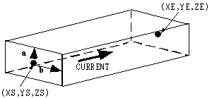
The current direction is the direction in which a right-handed screw advances when rotating from a to b.
17.1.4 Rectangular-cross-section arc current element ARC#
Specifies rectangular-cross-section arc current-element input.
Text-format section
- Type:
Fixed parameter set 1
- Number of lines:
1
- Number of parameters:
13
* ARC * CURRENT * X0 * Y0 * Z0 * RADIUS * AXIAL_W * RADIAL_W * ALPHA * BETA * PHI1 * PHI2 *
ARC    1.0      0.0  0.0  0.0  0.5     0.1      0.2       0.0    0.0   0.0    90.0
            "data" :
            [
                {
                    "type" : "ARC",
                    "CURRENT" : 1.0,
                    "XYZ" : [0.0, 0.0, 0.0],
                    "RADIUS" : 0.5,
                    "AXIAL_W" : 0.1,
                    "RADIAL_W" : 0.2,
                    "ALPHA" : 0.0,
                    "BETA" : 0.0,
                    "PHI1" : 0.0,
                    "PHI2" : 90.0
                }
            ]
ARC#
- ARC(17.1.4)#
Text-format section
[row, col] = [1, 1]
- Type:
String (S)
- Description:
Rectangular-cross-section arc current-element definition.
CURRENT#
- CURRENT(17.1.4)#
Text-format section
[row, col] = [1, 2]
- Type:
Real (E)
- Unit:
A
- Description:
Normalized current value.
For a wound coil, it may be easier to understand this value as the number of turns.
XYZ#
- XYZ(17.1.4)#
Text-format section
[row, col] = [1, 3]
- Type:
Real array (E)
- Unit:
m
- Number:
3
- Description:
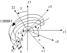
Arc-center coordinates.
RADIUS#
- RADIUS(17.1.4)#
Text-format section
[row, col] = [1, 4]
- Type:
Real (E)
- Unit:
m
- Description:
Arc-center radius.
AXIAL_W#
- AXIAL_W(17.1.4)#
Text-format section
[row, col] = [1, 5]
- Type:
Real (E)
- Unit:
m
- Description:
Axial width.
RADIAL_W#
- RADIAL_W(17.1.4)#
Text-format section
[row, col] = [1, 6]
- Type:
Real (E)
- Unit:
m
- Description:
Radial width.
ALPHA#
- ALPHA(17.1.4)#
Text-format section
[row, col] = [1, 7]
- Type:
Real (E)
- Unit:
deg
- Description:
Euler angle \(\alpha\) (rotation about the z1 axis).
BETA#
- BETA(17.1.4)#
Text-format section
[row, col] = [1, 8]
- Type:
Real (E)
- Unit:
deg
- Description:
Euler angle \(\beta\) (rotation about the x2 axis).
PHI1#
- PHI1(17.1.4)#
Text-format section
[row, col] = [1, 9]
- Type:
Real (E)
- Unit:
deg
- Description:
Start angle measured from the x2 axis \(\phi 1\).
PHI2#
- PHI2(17.1.4)#
Text-format section
[row, col] = [1, 10]
- Type:
Real (E)
- Unit:
deg
- Description:
End angle measured from the x2 axis \(\phi 2\).
Hint
It is easier to define a local coordinate system with zero Euler angles and enter the coil in that system than to specify the coil orientation with Euler angles in the global coordinate system.
17.1.5 Straight-line current element FGCE#
Specifies straight-line current-element input.
Text-format section
- Type:
Fixed parameter set 1
- Number of lines:
1
- Number of parameters:
7
* FGCE * CURRENT * XS * YS * ZS * XE * YE * ZE *
FGCE    1.0      0.0  0.0  0.0  1.0  1.0  1.0
            "data" :
            [
                {
                    "type" : "FGCE",
                    "CURRENT" : 1.0,
                    "S_XYZ" : [0.0, 0.0, 0.0],
                    "E_XYZ" : [1.0, 1.0, 1.0]
                }
            ]
FGCE#
- FGCE(17.1.5)#
Text-format section
[row, col] = [1, 1]
- Type:
String (S)
- Description:
Straight-line current-element definition.
CURRENT#
- CURRENT(17.1.5)#
Text-format section
[row, col] = [1, 2]
- Type:
Real (E)
- Unit:
A
- Description:
Normalized current value.
For a wound coil, it may be easier to understand this value as the number of turns.
S_XYZ#
- S_XYZ(17.1.5)#
Text-format section
[row, col] = [1, 3]
- Type:
Real array (E)
- Unit:
m
- Number:
3
- Description:
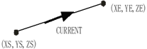
Start-point coordinates.
E_XYZ#
- E_XYZ(17.1.5)#
Text-format section
[row, col] = [1, 4]
- Type:
Real array (E)
- Unit:
m
- Number:
3
- Description:
End-point coordinates.
This element has zero cross-sectional dimensions for GCE(17.1.3). The field on the line is treated as zero. The field can become very large near the line. With GCE(17.1.3), a bend must be connected to ARC(17.1.4), whereas FGCE(17.1.5) does not require that connection unless an arc approximation is used. To use an arc approximation, use FARC(17.1.6).
17.1.6 Arc-line current element FARC#
Specifies arc-line current-element input.
Text-format section
- Type:
Fixed parameter set 1
- Number of lines:
1
- Number of parameters:
10
* FARC * CURRENT * X0 * Y0 * Z0 * RADIUS * ALPHA * BETA * PHI1 * PHI2 *
FARC    E        E    E    E    E       E      E      E      E
            "data" :
            [
                {
                    "type" : "FARC",
                    "CURRENT" : E,
                    "XYZ0" : [E, E, E],
                    "RADIUS" : E,
                    "ALPHA" : E,
                    "BETA" : E,
                    "PHI1" : E,
                    "PHI2" : E
                }
            ]
FARC#
- FARC(17.1.6)#
Text-format section
[row, col] = [1, 1]
- Type:
String (S)
- Description:
Arc-line current-element definition.
CURRENT#
- CURRENT(17.1.6)#
Text-format section
[row, col] = [1, 2]
- Type:
Real (E)
- Unit:
A
- Description:
Normalized current value.
For a wound coil, it may be easier to understand this value as the number of turns.
XYZ0#
- XYZ0(17.1.6)#
Text-format section
[row, col] = [1, 3]
- Type:
Real array (E)
- Unit:
m
- Number:
3
- Description:
Arc-center coordinates.
RADIUS#
- RADIUS(17.1.6)#
Text-format section
[row, col] = [1, 4]
- Type:
Real (E)
- Unit:
m
- Description:
Arc-center radius.
ALPHA#
- ALPHA(17.1.6)#
Text-format section
[row, col] = [1, 5]
- Type:
Real (E)
- Unit:
deg
- Description:
Euler angle \(\alpha\) (rotation about the z1 axis).
BETA#
- BETA(17.1.6)#
Text-format section
[row, col] = [1, 6]
- Type:
Real (E)
- Unit:
deg
- Description:
Euler angle \(\beta\) (rotation about the x2 axis).
PHI1#
- PHI1(17.1.6)#
Text-format section
[row, col] = [1, 7]
- Type:
Real (E)
- Unit:
deg
- Description:
Start angle measured from the x2 axis \(\phi 1\).
PHI2#
- PHI2(17.1.6)#
Text-format section
[row, col] = [1, 8]
- Type:
Real (E)
- Unit:
deg
- Description:
End angle measured from the x2 axis \(\phi 2\).
This element has zero cross-sectional dimensions for ARC(17.1.4). The field on the line is treated as zero. The field can become very large near the line. The parameters are defined in the same way as for ARC(17.1.4).
Hint
It is easier to define a local coordinate system with zero Euler angles and enter the coil in that system than to specify the coil orientation with Euler angles in the global coordinate system.
17.1.7 MESHED_COIL element#
Specifies MESHED_COIL element input.
Text-format section
- Type:
Fixed parameter set 1
- Number of lines:
1
- Number of parameters:
3
* MESH * CURRENT * MESH_ID *
MESH    1.0      1
            "data" :
            [
                {
                    "type" : "MESH",
                    "CURRENT" : 1.0,
                    "MESH_ID" : 1
                }
            ]
MESH#
- MESH(17.1.7)#
Text-format section
[row, col] = [1, 1]
- Type:
String (S)
- Description:
Definition of the
MESHED_COILelement.
CURRENT#
- CURRENT(17.1.7)#
Text-format section
[row, col] = [1, 2]
- Type:
Real (E)
- Unit:
A
- Description:
Normalized current value.
For a wound coil, it may be easier to understand this value as the number of turns.
MESH_ID#
- MESH_ID(17.1.7)#
Text-format section
[row, col] = [1, 3]
- Type:
Integer (I)
- Description:
Material ID in the COIL_geom file.
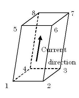
The MESHED_COIL element represents mesh input in which the coil geometry is constructed from hexahedral elements. A mesh file ( COIL_geom ) in the format specified by INPUT_MESH_FILE(10.1) is required. Specify electromagnetic-force output with COIL_FORCE(10.3).
Note
The current direction is defined from the bottom face (1-2-3-4) to the top face (5-6-7-8). The bottom and top faces do not have to be rectangular, but each must be defined on a single plane.
A distorted hexahedron cannot be defined with
GCE(17.1.3), but it can be defined withMESHED_COIL(17.1.7).If the geometry can be represented by
ARC(17.1.4)orGCE(17.1.3), defining it with one of those elements provides higher accuracy because it can be calculated analytically.This element is useful when analytical integration with
ARC(17.1.4)orGCE(17.1.3)diverges because of the relative position of the element and the finite-element mesh.Outputs the current-density distribution of
MESHED_COIL(17.1.7)elements to the COIL_current file for verification.
17.1.8 COIL integration elements#
Specifies COIL integration-element input.
Text-format section
- Type:
Fixed parameter set 1
- Number of lines:
1
- Number of parameters:
8
* COIL- * NDIV * INT_X * INT_Y * INT_Z *
LOOP-    1       5       5       3
            "data" :
            [
                {
                    "type" : "LOOP-",
                    "NDIV" : 1,
                    "INT_X" : 5,
                    "INT_Y" : 5,
                    "INT_Z" : 3
                },
                {
                    "type" : "GCE-",
                    "NDIV" : 1,
                    "INT_X" : 5,
                    "INT_Y" : 5,
                    "INT_Z" : 3
                },
                {
                    "type" : "ARC-",
                    "NDIV" : 1,
                    "INT_X" : 5,
                    "INT_Y" : 5,
                    "INT_Z" : 3
                }
                {
                    "type" : "MESH-",
                    "NDIV" : 1,
                    "INT_X" : 5,
                    "INT_Y" : 5,
                    "INT_Z" : 3
                }
            ]
LOOP-, GCE-, ARC-, MESH-#
- LOOP-(17.1.8)#
- GCE-(17.1.8)#
- ARC-(17.1.8)#
- MESH-(17.1.8)#
Text-format section
[row, col] = [1, 1]
Elements formed by adding a minus sign (-) after LOOP(17.1.2), GCE(17.1.3), ARC(17.1.4), or MESH(17.1.7).
Represents an integration region for inductance and electromagnetic force. Enter it as the same COIL series as the corresponding LOOP(17.1.2), GCE(17.1.3), ARC(17.1.4), or MESH(17.1.7).
Enter the normalized current and geometric dimensions in the same way as for the corresponding element.
NDIV#
- NDIV(17.1.8)#
Text-format section
[row, col] = [1, 2]
- Type:
Integer (I)
- Description:
Number of divisions in the current direction of the integration element. For
MESH-(17.1.8), enterNDIV= 1. ForLOOP-(17.1.8)withNDIV= 0 or 1, 12 is set automatically as a suitable default. ForARC-(17.1.8)withNDIV= 0 or 1, 12 / defined angle is set automatically as a suitable default.- Default value:
1
INT_X#
- INT_X(17.1.8)#
Text-format section
[row, col] = [1, 3]
- Type:
Integer (I)
- Description:
Number of Gaussian integration points in the X direction (the direction of vector a for
GCE-(17.1.8)and the radial direction forLOOP-(17.1.8)and ``ARC-(17.1.8)`).- Default value:
5
INT_Y#
- INT_Y(17.1.8)#
Text-format section
[row, col] = [1, 4]
- Type:
Integer (I)
- Description:
Number of Gaussian integration points in the Y direction (the direction of vector b for
GCE-(17.1.8)and the axial direction forLOOP-(17.1.8)and ``ARC-(17.1.8)`).- Default value:
5
INT_Z#
- INT_Z(17.1.8)#
Text-format section
[row, col] = [1, 5]
- Type:
Integer (I)
- Description:
Number of Gaussian integration points in the Z direction (the current direction).
- Default value:
3
Note
Electromagnetic-force output is divided into
NDIVequally spaced sections in the current direction.To output results divided in the coil cross-section direction, define each part separately.
The number of divisions and Gaussian integration points depends on the field distribution in the coil; choose them considering calculation time and accuracy. The maximum Gaussian integration order is 12.
For an axisymmetric two-dimensional calculation, enter the portion from -
DELTA_Z_THETA(12)/ 2 toDELTA_Z_THETA(12)/ 2 with respect toDELTA_Z_THETA(12). In this case,INT_Z= 1 is sufficient.For
MESH-(17.1.8), always set NDIV = 1 because the integration element cannot be divided more finely than the defined element.
17.1.9 Infinite straight-line current LINE#
Specifies infinite straight-line current input.
Text-format section
- Type:
Fixed parameter set 1
- Number of lines:
1
- Number of parameters:
8
* LINE * CURRENT * X0 * Y0 * Z0 * DX * DY * DZ *
LINE    E        E    E    E    E    E    E
            "data" :
            [
                {
                    "type" : "LINE",
                    "CURRENT" : E,
                    "XYZ0" : [E, E, E],
                    "DXYZ" : [E, E, E]
                }
            ]
LINE#
- LINE(17.1.9)#
Text-format section
[row, col] = [1, 1]
- Type:
String (S)
- Description:
Infinite straight-line current-element definition.
CURRENT#
- CURRENT(17.1.9)#
Text-format section
[row, col] = [1, 2]
- Type:
Real (E)
- Unit:
A
- Description:
Normalized current value.
XYZ0#
- XYZ0(17.1.9)#
Text-format section
[row, col] = [1, 3]
- Type:
Real array (E)
- Unit:
m
- Number:
3
- Description:
Coordinates of a point through which the line passes.
DXYZ#
- DXYZ(17.1.9)#
Text-format section
[row, col] = [1, 4]
- Type:
Real array (E)
- Unit:
None
- Number:
3
- Description:
Components of the line direction vector.
Caution
The current cross-section is treated as a point, and the field diverges to infinity near the line.
17.1.10 Dipole field DIPO#
Specifies dipole-field input.
Text-format section
- Type:
Fixed parameter set 1
- Number of lines:
1
- Number of parameters:
2
* DIPO * DBZDX *
DIPO    E
            "data" :
            [
                {
                    "type" : "DIPO",
                    "DBZDX" : E
                }
            ]
DIPO#
- DIPO(17.1.10)#
Text-format section
[row, col] = [1, 1]
- Type:
String (S)
- Description:
Dipole-field element definition.
DBZDX#
- DBZDX(17.1.10)#
Text-format section
[row, col] = [1, 2]
- Type:
Real (E)
- Unit:
T/m
- Description:
Normalized x-direction gradient of the z-direction magnetic field.
The magnetic field is given by the following equations.
Bx = DBZDX * z, By = 0, Bz = DBZDX * x.
Ax = 0, Ay = DBZDX/2 * (x**2 - z**2), Az = 0.
17.1.11 Permanent magnet EXMAG#
Specifies permanent-magnet input.
Text-format section
- Type:
Fixed parameter set 1
- Number of lines:
1
- Number of parameters:
2
* EXMAG * READ_OPTION *
EXMAG   I
* MAT_ID * COORD_ID * MXYZ *
  I   I   E    E    E
            "data" :
            [
                {
                    "type" : "EXMAG",
                    "READ_OPTION" : I,
                    "MAT_ID" : I,
                    "COORD_ID" : I,
                    "MXYZ" : [E, E, E]
                }
            ]
EXMAG#
- EXMAG(17.1.11)#
Text-format section
[row, col] = [1, 1]
- Type:
String (S)
- Description:
Permanent-magnet element definition.
READ_OPTION#
- READ_OPTION(17.1.11)#
Text-format section
[row, col] = [1, 2]
Value |
Description |
|---|---|
0 |
Read from the external ATLAS file EXMAG_magnetization. |
1 |
Read from the EXMAG_mesh file. |
Caution
When READ_OPTION = 1, the ATLAS file specified by INPUT_MESH_FILE(10.2) is required.
When READ_OPTION = 0, the external file EXMAG_magnetization is required. Because the behavior is undefined, contact support before using this option.
MAT_ID#
- MAT_ID(17.1.11)#
Text-format section
[row, col] = [2, 1]
- Type:
Integer (I)
- Description:
Material ID in the EXMAG_geom file.
COORD_ID#
- COORD_ID(17.1.11)#
Text-format section
[row, col] = [2, 2]
- Type:
Integer (I)
- Description:
Coordinate-system ID in the EXMAG_geom file (
COORD_ID(12)).
MXYZ#
- MXYZ(17.1.11)#
Text-format section
[row, col] = [2, 2]
- Type:
Real array (E)
- Unit:
T
- Description:
Components of the magnetization vector.
The EXMAG element represents mesh input in which a permanent-magnet geometry that supplies a magnetization distribution is constructed from hexahedral elements. A mesh file ( EXMAG_geom ) in the format specified by INPUT_MESH_FILE(10.1) is required. Because the magnetization vector is specified by MXYZ, a nonuniform magnetization distribution cannot be assigned.
Important
Because the EXMAG element is a COIL, it supplies permanent-magnet-equivalent magnetization as an external field source. Therefore, self-demagnetization and magnetization changes caused by an external magnetic field are not considered.