
Appendix 2: Current and Magnetic Field Sources#
EMSolution can define various current and magnetic field sources. The following lists these sources and their differences. For details, see the description of each module.
1. Types and Descriptions of Current and Magnetic Field Sources#
Current and magnetic field source |
Description |
|---|---|
Element current source ELMCUR |
Specify conductor volume elements created in the total-potential region and apply a uniform current. Hexahedral and triangular-prism elements can be used as conductor elements. For a hexahedron, any opposing faces can be the current inlet and outlet; for a triangular prism, only faces 1 and 2 can be used. |
Surface-defined current source SDEFCOIL |
Define a rectangular current path surrounding conductor volume elements created in the total-potential region with surface elements, and apply a uniform current. Define the rectangular path using four surface-element properties. Any type of conductor element can be used. |
Potential current source PHICOIL/DCCURR |
Define surface elements on one of the conductor’s Bn=0 symmetry-boundary faces in the total-potential region as the inlet face [1], and use the other Bn=0 symmetry face as the outlet face (no surface-element definition is required for the outlet face). The steady current-density distribution is defined from the gradient of the electric scalar potential within the conductor between the inlet and outlet faces. You can also define a gap element in part of a loop conductor to specify the inlet face. |
Surface current source SUFCUR |
Define surface elements on one of the conductor’s symmetry-boundary faces in the total-potential region as the inlet face [1], and use the other Bn=0 symmetry face as the outlet face (no surface-element definition is required for the outlet face). Solve the coil region as an eddy-current field using the circuit voltage between the inlet and outlet faces and the surrounding magnetic field to obtain the internal current distribution. You can also define a gap element in part of a loop conductor to specify the inlet face. This source cannot be used for magnetostatic analysis. It is also used to fix the current crossing a defined face at zero. |
External current source COIL |
Define a current and magnetic field source separately from the finite elements in the reduced-potential region. Part or all of the COIL may be outside the reduced-potential region. It can be moved independently of the finite elements. |
[1] The inlet face is the face to which the positive-side voltage of the power supply is applied.
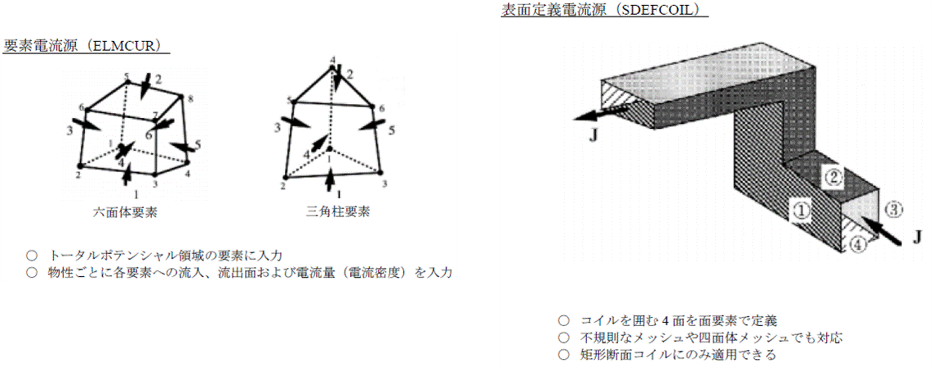
Surface-element definition#
2. Guidelines for Selecting Current and Magnetic Field Sources#
Current and magnetic field source |
Applicable coil type |
Type |
Applicable analysis modes |
|
|---|---|---|---|---|
Wound coil (uniform current) |
Bulk conductor (distributed current) |
|||
Element current source ELMCUR |
○ |
× |
Internal magnetic field source for applying uniform current |
Static, AC, Transient, Steady-Current |
Surface-defined current source SDEFCOIL |
○ |
× |
Internal magnetic field source for applying uniform current |
Static, AC, Transient, Steady-Current |
Potential current source PHICOIL/DCCURR [5] |
○/△ [2] |
○/△ [3] |
Internal magnetic field source for applying quasi-uniform current |
Static, AC, Transient, Steady-Current |
Surface current source SUFCUR |
×/○ [4] |
○ |
Internal magnetic field source for distributed current in a conductor |
AC, Transient, Steady-Current |
External current source COIL |
○ |
× |
External magnetic field source for applying uniform current |
Static, AC, Transient, Steady-Current |
[2] Current becomes distributed in bent sections.
[3] Applicable only to a constant DC current. Use SUFCUR to calculate distributed current that accounts for skin effect or eddy currents.
[4] Not applicable when modeled as a winding shape; applicable when modeled using individual wire shapes.
[5] Use DCCURR for a conductor in which materials with different conductivities are in contact.
Current and magnetic field source |
2D/3D |
Available element types |
Current distribution in the coil cross section |
Applicable coil cross-sectional shape” |
|---|---|---|---|---|
Element current source ELMCUR |
2D is easier to apply” |
Hexahedra and triangular prisms only [6] |
Uniform |
Arbitrary cross section |
Surface-defined current source SDEFCOIL |
3D |
Volume elements (defined by surface elements) |
Uniform |
Rectangular cross section; trapezoidal cross section is also allowed *Hint |
Potential current source PHICOIL/DCCURR |
2D & 3D. Uniform for 2D translational symmetry; biased toward the axis for 2D axial symmetry. |
Volume elements (defined by surface elements) |
Uniform in straight sections; biased toward the inside in curved sections. |
Arbitrary cross section |
Surface current source SUFCUR |
2D & 3D |
Volume elements (defined by surface elements) |
Distribution including eddy currents |
Arbitrary cross section |
External current source COIL |
2D & 3D |
For a MeshedCOIL that does not use finite elements, define it with hexahedral elements separately from the finite elements. |
Uniform |
Rectangular cross section. For a MeshedCOIL, a trapezoidal cross section can also be used. |
[6] A triangular prism can be used when the coil-side cross section is triangular. The principle of a constant element cross-sectional area must also be maintained.
Current and magnetic field source |
Definition method |
Method for specifying the current direction |
Hints |
|---|---|---|---|
Element current source ELMCUR |
Apply to an arbitrary cross-sectional shape made of hexahedra with matching cross-sectional areas for all elements. |
Specify the current direction by the element-definition direction of the hexahedra or triangular prisms. |
A constant cross-sectional area must be maintained along the current path. When OPTION=0, every element must also have a constant cross-sectional area. |
Surface-defined current source SDEFCOIL |
Surround the rectangular coil surface made of volume elements with surface elements. The surface-element normals point inward. |
Specify the current direction in right-hand-screw order using four surface-element IDs. |
Use this magnetic field source for wound coils. A trapezoidal cross section can be used, but the current will not be uniform. |
Potential current source PHICOIL/DCCURR |
Apply surface elements to one coil cross section (a symmetry-boundary face) made of volume elements. For a loop coil, use a gap element to specify the definition face. |
The normal direction of the defined surface element is the positive direction. |
It can also be applied to cross sections other than rectangular ones. However, current is distributed in bent sections, so homogenization measures may be required depending on the required accuracy. PHICOIL cannot establish electrical contact between materials with different material-property IDs; use DCCURR instead. |
Surface current source SUFCUR |
Not available for Static analysis. PHICOIL can be used instead. Apply current-input/output surface elements to one coil cross section (a symmetry-boundary face) made of solid elements. For a loop conductor, use a gap element to specify the definition face. |
The normal direction of the defined surface element is the positive direction. Create a conductor mesh that accounts for skin effect. |
Applicable only to analyses that include eddy currents. It can also be used for analyses that fix the current crossing a defined face at zero. |
External current source COIL |
Define it in the reduced-potential region or outside the finite elements. Enter the shape using coordinate values, or create it with hexahedral elements (MeshedCOIL). For voltage input, calculate the air-core inductance using CALC_IND. |
For shape input, the specified direction is positive. For MeshedCOIL, the hexahedral-element definition direction is positive. |
Because the magnetic field distribution is calculated using the Biot-Savart law at the boundary between the total-potential and reduced-potential regions, placing magnetic material too close to a COIL can affect calculation accuracy. |
Supplementary Notes#
Item |
Description |
|---|---|
Setting current and number of turns |
When the coil normalized current equals the number of turns, external current × number of turns equals the coil cross-sectional current. Specify the time functions for current and voltage in CIRCUIT/NETWORK. |
Calculating inductance |
When connected to a power supply through CIRCUIT or NETWORK, calculate inductance by dividing the magnetic flux (Flux) in the output file by the current (Current). For a COIL, the air-core inductance is output before step calculation in the output file when CALC_IND=1. |
Current continuity condition |
Current must be continuous, including across boundary conditions (divJ=0). Therefore, specify symmetry boundary conditions on the inlet and outlet faces of ELMCUR, SDEFCOIL, PHICOIL, and SUFCUR, which are defined as meshes. A COIL must also be closed; because mesh symmetry conditions do not apply, define it as a full model (with exception [7]). When the current enters and exits far away, as in a busbar, the COIL need not be closed if it is extended sufficiently far from the mesh (REGULARIZATION=1 is required). |
Coil resistance |
SUFCUR solves the bulk-conductor region as an eddy-current field, so always specify conductivity SIGMA. Conductor resistance is not calculated directly; evaluate it from the eddy-current loss heat. For ELMCUR, SDEFCOIL, and PHICOIL, eddy currents are not considered even if SIGMA is specified for the coil region. Specifying SIGMA outputs the coil resistance, accounting for the number of turns, to the output file. Calculate Joule loss in the coil as I2R from the coil resistance and coil current. Alternatively, for ELMCUR, SDEFCOIL, and PHICOIL, set SIGMA to 0 and specify the coil resistance as an external resistance. Use an external resistance when considering coil resistance for COIL. |
[7] When Ωr does not contact the periodic boundary face, a COIL defined only in the mesh region can be used.