
17.8 Power Supplies and Connections (CIRCUIT)#
Input for defining an external electrical circuit.
CIRCUIT defines current-field sources, power supplies, external resistances, and external inductances using a connection matrix.
Settings#
CIRCUIT(17.8) JSON key: power-supply and connection object
REGION_FACTOR(17.8)Indicates that the actual system (full model) represented by the analysis is this multiple of the analysis-model region.
REGION_PARALLEL(17.8)Sets the number of parallel circuits (default: 1).
INDUCTANCE_MATRIX(17.8)Defines the inductance matrix.
SERIES_IDS(17.8)Series IDs.
IN_IND(17.8)External-inductance matrix input method
MATRIX(17.8)Inductance matrix
RESISTANCE_MATRIX(17.8)Defines the resistance matrix.
IN_RES(17.8)External-resistance matrix input method
MATRIX(17.8)Resistance matrix
CONNECTION_MATRIX(17.8)Connection matrix.
IN_CON(17.8)External-connection matrix input method
MATRIX(17.8)Connection matrix
POWER_SUPPLIES(17.8)Defines power supplies.
PS_ID(17.8)Power-supply identifier.
TYPE(17.8)Power-supply type.
TIME_ID(17.8)Time-definition ID used when a time-dependent current is specified.
INITIAL_CURRENT(17.8)Initial current (A) of a constant-voltage power supply in transient analysis (when TRANSIENT(2) is enabled).
Input format#
Text-format section
- Type:
Fixed parameter set 1
- Number of lines:
3~6
- Number of parameters:
7, NO_SERIES, 1, 1, 1, NO_POWER_SUPPLIES
* CIRCUIT *
CIRCUIT
* NO_SERIES * NO_POWER_SUPPLIES * REGION_FACTOR * IN_IND * IN_RES * IN_CON*
    1              1                 8      1      1      0               0
* SERIES_IDS *
1
* SERIES_EXTERNAL_INDUCTANCE *
            0
* SERIES_EXTERNAL_RESISTANCE *
            0
* CONNEXION MATRIX *
            1
* POWER_SUPPLY_ID * TYPE * TIME_ID * INITIAL_CURRENT*
    1     0     1              0
END
JSON format#
"17_Field_Source" :
[
    {
        "CIRCUIT" :
        {
            "REGION_FACTOR" : E,
            "REGION_PARALLEL" : E,
            "SERIES_IDS" : [ I ],
            "INDUCTANCE_MATRIX" :
            {
                "comment" : "IN_IND=0: lower triangular matrix. \n IN_IND=1: diagonal matrix. IN_ID=2 : not defined.",
                "format" : "[1st row][2nd row][3rd row]",
                "IN_IND" : I,
                "MATRIX" : [ E ]
            },
            "RESISTANCE_MATRIX" :
            {
                "comment" : "IN_IND=0: lower triangular matrix. \n IN_IND=1: diagonal matrix. IN_ID=2 : not defined.",
                "format" : "[1st row][2nd row][3rd row]",
                "IN_RES" : I,
                "MATRIX" : [ E ]
            },
            "CONNECTION_MATRIX" :
            {
                "comment" : "IN_CON=0: NO_SERIES * NO_POWER_SUPPLIES connection matrix. \n IN_CON=1: diagonal connection matrix.",
                "IN_CON" : I,
                "format" : "[1st row][2nd row][3rd row]",
                "MATRIX" :
                [
                    [ E ]
                ]
            },
            "POWER_SUPPLIES" :
            [
                {
                    "PS_ID" : I,
                    "TYPE" : I,
                    "TIME_ID" : I,
                    "INITIAL_CURRENT" : E
                }
            ]
        }
    }
]
Detailed description#
CIRCUIT connects current-field sources, power supplies, external resistances, and external inductances using a connection matrix.
Hint
For a single-phase power supply, the connection matrix is a simple one-row, one-column matrix.
For a three-phase wye connection, a 3-by-3 connection matrix is required. NETWORK(17.9) can represent this connection more simply.
CIRCUIT#
- CIRCUIT(17.8)#
Text-format section
[row, col] = [1, 1]
- Type:
String (S)
- Description:
Specifies the external circuit
CIRCUIT.
REGION_FACTOR#
- REGION_FACTOR(17.8)#
Text-format section
[row, col] = [2, 3]
- Type:
Real (E)
- Analysis:
Indicates that the actual system being analyzed (the full model) is this multiple of the analysis-model region.
For example, the value is 2N for mirror symmetry and N-fold rotational symmetry. This is required to enter the series external inductance, resistance, and voltage as full-model values. The output voltage is also reported for the full model.
When this value is entered as 1.0, input and output use the analysis-model region as the full system. In the example above, values of 1/2N must be entered for the corresponding full-model quantities, and the output voltage is for the analysis-model region.
REGION_PARALLEL#
- REGION_PARALLEL(17.8)#
Text-format section
[row, col] = [2, 7]
- Type:
Real (E)
- Description:
Sets the number of parallel circuits. The default is 1, and explicitly specifying
1in JSON is recommended.0can also be entered, but EMSolution treats it internally as1.
When REGION_FACTOR is set to the full-model multiple relative to the analysis model, the REGION_FACTOR conversion is applied so that the calculation corresponds to one parallel circuit. In this case, output reports power-supply values for the full model and coil and inductance values for one parallel circuit.
SERIES_IDS#
- SERIES_IDS(17.8)#
Text-format section
[row, col] = [7, 1]
- Type:
Integer (I)
- Description:
Series IDs.
INDUCTANCE_MATRIX#
- INDUCTANCE_MATRIX(17.8)#
Definition of the external-inductance matrix.
IN_IND#
- IN_IND(17.8)#
Text-format section
[row, col] = [2, 4]
Value |
Description |
|---|---|
0 |
Enter the lower-triangular matrix. Default value |
1 |
Enter only the diagonal components; off-diagonal terms are set to zero. |
2 |
Assume that there is no external inductance. |
MATRIX#
- MATRIX(17.8)#
Text-format section
SERIES_EXTERNAL_INDUCTANCE
[row, col] = [3, 1]
Type=[ E ]
- When
IN_IND= 0 External-inductance matrix. The self- and mutual inductances ( \(H\) ) outside the finite-element region for each source-term series. Inductance values are normalized by the normalized current value (
CURRENT(17)) specified for the source term. The matrix is symmetric; enter its lower half.In the
NO_SERIESrows of data, row I contains I data values.The total number of data values is
NO_SERIES* (NO_SERIES+ 1) / 2.
- When
- When
IN_IND= 1 Enter only the diagonal components. The number of data values is NO_SERIES.
- When
When
IN_IND= 2, no input is required.
Caution
For a
COIL(17.1)source term, setCALC_IND(4)= 1 and enterCOIL(17.1)withMESH(17.1.7)COIL integration elements (LOOP-(17.1.8),GCE-(17.1.8), orARC-(17.1.8)). The self-inductance of the coil and mutual inductances between coils are calculated internally and added.For
COIL(17.1)when the above input is not used, the self-inductance ofCOIL(17.1)and mutual inductance between COILs are not considered in the finite-element region. Therefore, they must be entered as external inductance to obtain actual input and output voltages.If the external inductance is set to 0 in the above case, the voltage is the linked flux of the induced field from the total-potential region and the fields from other source terms.
Enter inductance connected externally in series with the series, including leakage inductance.
RESISTANCE_MATRIX#
- RESISTANCE_MATRIX(17.8)#
Definition of the external-resistance matrix.
IN_RES#
- IN_RES(17.8)#
Text-format section
[row, col] = [2, 5]
Value |
Description |
|---|---|
0 |
Enter the lower-triangular matrix. Default value |
1 |
Enter only the diagonal components; off-diagonal terms are set to zero. |
2 |
Assume that there is no external resistance. |
- MATRIX(17.8)#
Text-format section
SERIES_EXTERNAL_RESISTANCE
[row, col] = [4, 1]
- When
IN_RES= 0 External-resistance matrix. The self- and mutual resistances (\(\Omega\)) outside the finite-element region for each source-term series. Resistance values are normalized by the normalized current value (
CURRENT(17)) specified for the source term. The matrix is symmetric; enter its lower half.In the
NO_SERIESrows of data, row I contains I data values.The total number of data values is
NO_SERIES* (NO_SERIES+ 1) / 2.
- When
- When
IN_RES= 1 Enter only the diagonal components. The number of data values is
NO_SERIES.
- When
When
IN_RES= 2, no input is required.
Caution
For a
COIL(17.1)source, enter the resistance ofCOIL(17.1).For
ELMCUR(17.2)andSDEFCOIL(17.3), the resistance is considered when the values ofSIGMA(17.2)andSIGMA(17.3)are entered. SettingSIGMA= 0 and entering the resistance here has the same effect.For
SUFCUR(17.6), do not add the resistance of the finite-element region in this input.
CONNECTION_MATRIX#
- CONNECTION_MATRIX(17.8)#
Connection matrix.
IN_CON#
- IN_CON(17.8)#
Text-format section
[row, col] = [5, 1]
Value |
Description |
|---|---|
0 |
Enter the connection matrix ( |
1 |
When |
- MATRIX(17.8)#
Text-format section
CONNECTION_MATRIX
[row, col] = [6, 1]
Matrix representing the connection between each series and power supply.
- When
IN_CON= 0: This is a matrix with
NO_SERIESrows andNO_POWER_SUPPLIEScolumns. The series current/voltage vector (i, v) and the power-supply current/voltage vector (I, V) are related by thisCONNECTION_MATRIXT as i = TI and V = Ttv. Tt is the transpose matrix.
- When
When
IN_CON= 1: no input is required.
Hint
When the number of series and power supplies is the same and they are powered independently, use the identity matrix (diagonal terms are 1.0 and all other terms are 0.0).
This connection representation and matrix allow arbitrary coupling between sources.
POWER_SUPPLIES#
- POWER_SUPPLIES(17.8)#
- JSON key:
Power-supply object
Power-supply definition.
PS_ID#
- PS_ID(17.8)#
Text-format section
[row, col] = [7, 1]
- Type:
Integer (I)
- Description:
Power-supply identifier.
TYPE#
- TYPE(17.8)#
Text-format section
[row, col] = [7, 2]
Value |
Description |
|---|---|
0 |
Constant-current power supply (current variation is specified and voltage is unknown). |
1 |
Constant-voltage power supply (voltage variation is specified and current is unknown). |
TIME_ID#
- TIME_ID(17.8)#
Text-format section
[row, col] = [7, 3]
- Type:
Integer (I)
- Description:
Data ID specifying the time variation of the power-supply current (when
TYPE= 0) or voltage (whenTYPE= 1) (TIME_ID(18)).
A value of 0 indicates a constant value.
INITIAL_CURRENT#
- INITIAL_CURRENT(17.8)#
Text-format section
[row, col] = [7, 4]
- Type:
Real (E)
- Unit:
A
- Description:
Initial current of a constant-voltage power supply in transient analysis (when
TRANSIENT(2)is enabled). During a restart, if this power supply was also a constant-voltage source in the initial run, setting this to =999. uses the result of the initial run as the initial value.
Note
For a closed circuit (the two coil terminals are shorted), assume that a 0-voltage constant-voltage power supply is connected.
For an open circuit (the two coil terminals are disconnected), assume that a 0-current constant-current power supply is connected.
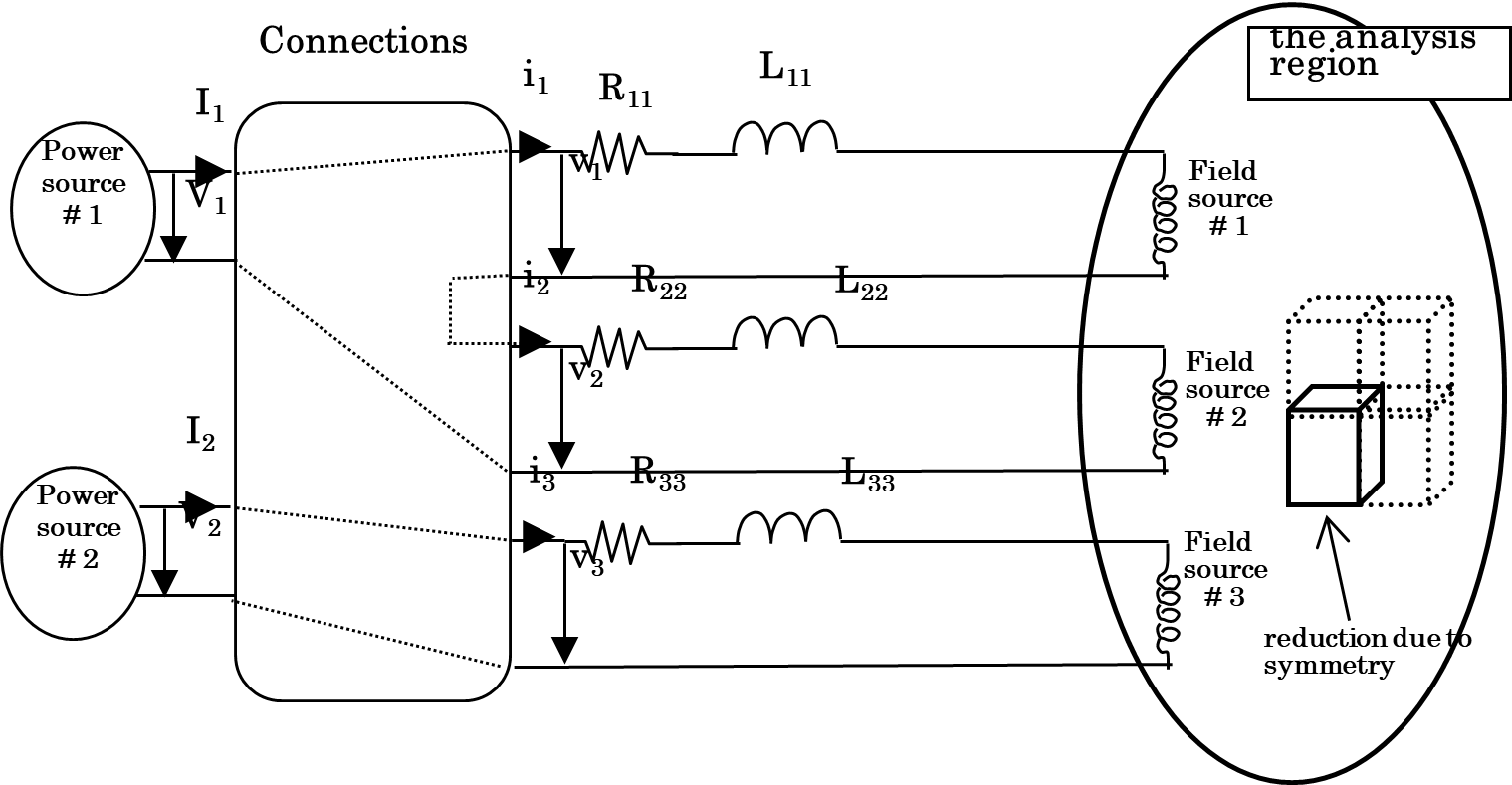
The figure below shows an example connection with two power supplies and three field coils. The
CIRCUIT(17.8)data is as follows.
Text-format section
[row, col] = [1, 1]
Type=S
CIRCUIT *
CIRCUIT * NO_SERIES * NO_POWER_SUPPLIES * REGION_FACTOR * IN_IND * IN_RES * IN_CON*
3 2 4.0 0 0 0 0
- SERIES_IDS *
1 2 3
- SERIES_EXTERNAL_INDUCTANCE *
L11 L12 L22 L13 L23 L33
- SERIES_EXTERNAL_RESISTANCE *
R11 R12 R22 R13 R23 R33
- CONNECTION MATRIX *
1. 0. 1. 0. 0. 1.
"17_Field_Source" :
[
    {
        "CIRCUIT" :
        {
            "REGION_FACTOR" : 4.0,
            "REGION_PARALLEL" : 1,
            "SERIES_IDS" : [ 1, 2, 3 ],
            "INDUCTANCE_MATRIX" :
            {
                "comment" : "IN_IND=0: lower triangular matrix. \n IN_IND=1: diagonal matrix. IN_ID=2 : not defined.",
                "format" : "[1st row][2nd row][3rd row]",
                "IN_IND" : 0,
                "MATRIX" : [ L11, L12, L22, L13, L23, L33 ]
            },
            "RESISTANCE_MATRIX" :
            {
                "comment" : "IN_IND=0: lower triangular matrix. \n IN_IND=1: diagonal matrix. IN_ID=2 : not defined.",
                "format" : "[1st row][2nd row][3rd row]",
                "IN_RES" : 0,
                "MATRIX" : [ R11, R12, R22, R13, R23, R33 ]
            },
            "CONNECTION_MATRIX" :
            {
                "comment" : "IN_CON=0: NO_SERIES * NO_POWER_SUPPLIES connection matrix. \n IN_CON=1: diagonal connection matrix.",
                "IN_CON" : 0,
                "format" : "[1st row][2nd row][3rd row]",
                "MATRIX" :
                [
                    [ 1., 0. ],
                    [ 1., 0. ],
                    [ 0., 1. ]
                ]
            },
Example definition of CIRCUIT#