
17.3 Surface-Defined Current Source#
Defines a coil region in the finite-element mesh and assigns a uniform current density to the elements in that region. The coil region can have a rectangular cross-section.
Settings#
SDEFCOIL(17.3) JSON key: surface-defined current source object
SERIES_ID(17.3)Series ID.
IN_ROTOR(17.3)Flag indicating whether the defined region is in the rotor.
MAT_ID(17.3)Material ID assigned to the region.
SMAT_IDS(17.3)Material IDs of the faces surrounding the conductor.
CURRENT(17.3)Normalized current value.
SIGMA(17.3)Element conductivity
CAL_Je(17.3)Flag indicating whether eddy currents in the defined region are considered
Input format#
Text-format section
- Type:
Fixed parameter set 1
- Number of lines:
2
- Number of parameters:
4, 7
* SDEFCOIL * SERIES_NO * NO_PARTS * OPTION *
SDEFCOIL       I          I            I
* MAT_ID * S_ID1 * S_ID2 * SID_3 * SID_4 * CURENT * SIGMA *
    I       I        I       I      I        E        E
JSON format#
"17_Field_Source" :
[
    {
        "SDEFCOIL" :
        {
            "SERIES_ID" : I,
            "IN_ROTOR" : I,
            "data" :
            [
                {
                    "MAT_ID" : I,
                    "SMAT_IDS" : [ I, I, I, I ],
                    "CURRENT" : E,
                    "SIGMA" : E,
                    "CAL_Je" : I
                }
            ]
        }
    }
]
Detailed description#
SDEFCOIL defines the four faces of a rectangular-cross-section coil region and makes the current density uniform in the elements within that region. It can also define a trapezoidal-cross-section coil region; the current density is somewhat nonuniform, but the total current does not change.
Hint
In two-dimensional analysis, SDEFCOIL is particularly useful for axisymmetric calculations.
In three-dimensional analysis, SDEFCOIL is useful for modeling motor coils including the coil ends and for modeling transformer coils.
SDEFCOIL#
- SDEFCOIL(17.3)#
Text-format section
[row, col] = [1, 1]
- Type:
String (S)
- Description:
Specifies the surface-defined current source
SDEFCOIL.
SERIES_ID#
- SERIES_ID(17.3)#
Text-format section
[row, col] = [1, 2]
- Type:
Integer (I)
- Description:
Source-term identifier.
IN_ROTOR#
- IN_ROTOR(17.3)#
Text-format section
[row, col] = [1, 3]
Value |
Description |
|---|---|
0 |
In the fixed part. Default value |
1 |
In the moving part. |
Required for steady AC analysis with slip caused by sliding motion when N_CORRECT(8) ≠ 0.
data#
- data(17.3)#
- JSON key:
Surface-defined current source data
data is an array with one entry for each SDEFCOIL element.
MAT_ID#
- MAT_ID(17.3)#
Text-format section
[row, col] = [2, 1]
- Type:
Integer (I)
- Description:
Material ID of the elements to which the surface-defined current source is assigned (
MAT_ID(16.1)).
SMAT_IDS#
- SMAT_IDS(17.3)#
Text-format section
[row, col] = [2, 2]
- Type:
Integer array (I)
- Number:
4
- Description:
Material IDs of the faces surrounding the conductor. Specify them in an array in the right-handed order relative to the current direction.
“SMAT_IDS” : [ 1, 2, 3, 4 ]
The direction toward the front of the page is positive
1: Top face
2: Left face
3: Bottom face
4: Right face
CURRENT#
- CURRENT(17.3)#
Text-format section
[row, col] = [2, 3]
- Type:
Real (E)
- Unit:
A
- Description:
Normalized current passing through the face.
For a wound coil, it may be easier to understand this value as the number of turns.
SIGMA#
- SIGMA(17.3)#
Text-format section
[row, col] = [2, 4]
- Type:
Real (E)
- Unit:
\(S/m\)
- Description:
Electrical conductivity of the element. The series resistance is calculated.
CAL_Je#
- CAL_Je(17.3)#
Text-format section
[row, col] = [2, 5]
Value |
Description |
|---|---|
0 |
Do not consider eddy currents in the defined region Default value |
1 |
Considers eddy currents in the defined region. The conductivity specified by |
Caution
Surface-defined current-source input is effective for rectangular-cross-section coils. The elements must be in the total-potential region.
Assign a material ID to the volume elements of the coil conductor. The conductor may be divided into parts with different material IDs. Define the four surrounding faces of the coil-conductor region as surface elements and assign a different material ID to each face. Define the surface-element orientations toward the inside of the coil conductor.
The
MAT_ID(16.1)values must be defined in the input mesh data file. For these material definitions, setSIGMA(16.1)= 0 andMU(16.1)= 1.0.Connection to
CIRCUIT(17.8)orNETWORK(17.9)is required.
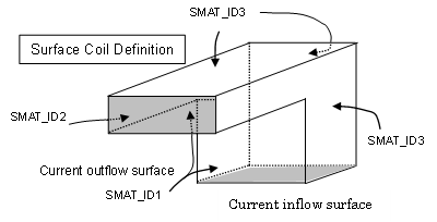
Example definition of SDEFCOIL#